The transformer is a crucial equipment in the power system, which realizes efficient conversion between different voltages through electromagnetic induction to ensure the safe transmission of power to all kinds of equipment. In this article, we will briefly introduce the basic principles, structure, and application scenarios of transformers to help you quickly understand the core knowledge of transformers.
Figure 1 What is transformer
Transformer Definition
What is a Transformer?

Figure 1-1 Transformer diagram
A transformers meaning, essential, purpose of a transformer is a device used to convert alternating current between different voltages. In a power system, the voltage of the current often needs to be adjusted up or down – for example, transformers are a device that increases or decreases voltage. high voltage is needed to minimize losses when transmitting from a power station to a city, and reduced voltage is needed for safety when it reaches a house or a factory. transformers function are the devices that play a key role in this “high and low voltage conversion”.
Case: What is function of transformer ? Imagine a city power system where power is transmitted from distant power stations at voltages that may be as high as hundreds of thousands of volts in order to minimize losses in the transmission of power. However, this high voltage obviously does not go directly to household appliances. Therefore, once the power reaches the city substation, the voltage is regulated to a suitable level, say 220 volts, by means of a step down transformer to ensure the safety and proper functioning of the equipment.
Transformer Working Principle

Figure 1-2 Diagram for transformer
The principle of operation of a transformer is based on electromagnetic induction. A typical transformer has two windings, called the primary winding and the secondary winding, which are usually wound on the same core. When an alternating current flows through the primary winding, an alternating magnetic field is generated, which in turn induces a voltage in the secondary winding. This process is contactless and relies on the “remote” effect of electromagnetic induction. The main operating principle of transformers is electromagnetic induction, which allows voltage to change between circuits.
The ratio of the number of turns of the windings determines the voltage increase or decrease. For example, if the primary windings have more turns than the secondary windings, the voltage of the secondary windings will be lower than that of the primary; on the contrary, the voltage will rise. This principle of contactless voltage conversion makes the transformer a key component for safety and reliability in power systems.
Case in point: How do electric transformers work? For example, small chargers in appliances often include a 12v ac transformer through which, when plugged in, 220 volts is stepped down to 5, 9, or 12 volts, which is exactly the low voltage needed for a cell phone or laptop to charge safely.
Why Are Transformers Critical to the Power System?
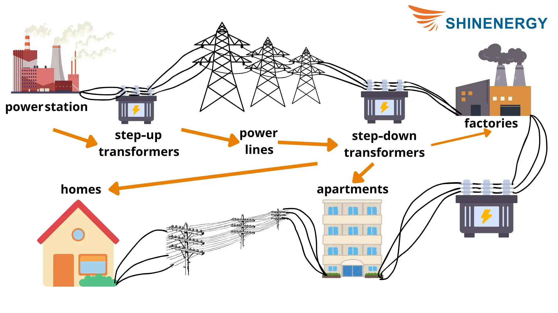
Figure 1-3 electrical transformer photo
purpose of transformer: Transformers are the cornerstone of modern power systems. Their presence allows power to be transmitted efficiently at different voltages without worrying about excessive energy loss in transmission. High-voltage transmission not only saves energy but also reduces the overall cost of power transmission. In addition, transformers spread the load in the grid and reduce the risk of single-point failures.
Case: What does a transformer do? In high-rise buildings and large industrial parks, transformers are not only responsible for stepping down the voltage but also for supplying power to different areas through a distributed layout.
How to Construct a Transformer?
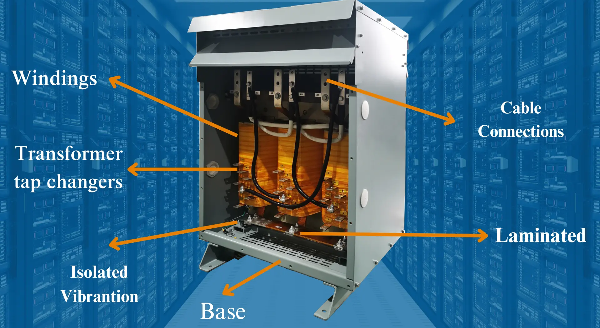
Figure 2- 1 transformer construction
The Role of the Iron Core and Material Selection

Figure 2-2 transformer core
The transformer coil is the central component of the transformer and its main function is to “steer” the magnetic field to ensure more efficient electromagnetic induction. The choice of core material is critical as it determines the energy loss and efficiency of the transformer. Most transformers use silicon steel sheets for the core because of their high permeability and low loss properties, which reduce energy loss in an alternating magnetic field.
Case: What does the power transformer do? To clarify, we often get asked, ‘Is the power supply and the transformer the same thing?’ by new technicians. In high-frequency transformers (e.g., transformers in electronic equipment), ferrite materials are often used instead of silicon steel. This is because ferrite has lower magnetic losses at high frequencies and is therefore suitable for higher frequency environments. The difference between the advantages and disadvantages of different materials in different applications is part of the balance and consideration that needs to be taken into account when designing.
Transformer Windings and Transformer Insulation

Figure 2-3 Transformer Windings
Windings are the part of the transformer responsible for transferring current and are usually made of copper or aluminum conductors. Copper is commonly used in transformers that require high efficiency due to its good conductivity and low losses, while aluminum is usually used in application scenarios that do not require high efficiency due to its lower price.

Figure 2-4 transformer insulation
Windings need to be covered with insulating material to avoid short circuits and current leakage. The choice of insulating material should not only take into account the insulating properties but also need to cope with the heat inside the transformers. In general, common insulating materials include paper, resin, and polyester film.
Example: What do transformers do? Heat-resistant resin insulation is commonly used in high-voltage transformers to ensure that the insulation is not degraded by overheating after a long period of operation, which would affect the life and safety of the transformers.
Transformer Cooling System

Figure 2-5 Transformer cooling types
Transformers generate a large amount of heat during operation and therefore require a cooling system to control the temperature and avoid damage to the components due to excessive temperature rise. The main cooling methods are natural air cooling, forced air cooling, and oil cooling.
- Natural air cooling: commonly used for small dry-type transformers, relying on airflow to carry away heat.
- Forced air cooling
- Transformer cooling oil
**Case:** In large power plants, oil immersion cooling systems are common because power generation equipment generates more current and more heat. The oil cooling system can effectively control the temperature, extend the service life of the equipment, and ensure the stable operation of the power plant.
Other Transformer Component

Figure 2-6 Transformer components
In addition to the core, windings, and cooling system, transformers have a number of other key components:
- Transformer enclosure
- Terminal connector
- Pressure relief valves
Case: Protective enclosures are particularly important for commercial transformer installed outdoors, especially in windy or humid areas. By using a sealed design and corrosion-resistant materials, the enclosure protects the transformers from stable operation in bad weather.
Types of Transformers
Different types of transformers
| utility pole transformers | electricity transformers | illustrated transformers | define transformers |
| powerline transformers | Isolation Transformers | Step Up and Step Down Transformers | electrical transformers |
| control transformers | dry type transformers | Autotransformers | oil immersed transformers |
Difference Between dry type transformer and oil immersed transformer

Figure 3-1 difference between dry type transformer and oil immersed transformer
Dry type transformers and oil immersed transformers are the two most common types, the difference between them lies mainly in the cooling method and the applicable environment.
Dry type transformer: relies on air or forced air cooling, eliminating the need for cooling oil. dry type transformers usually offer a high level of safety and are particularly suitable for environments with high fire protection requirements, such as shopping malls, hospitals, and interior installations in high-rise buildings. With no risk of oil leakage, they have lower maintenance requirements but require special protection against moisture in humid environments.
Oil immersed transformer: transformer oil is used for cooling, and the oil also acts as an insulator. This type of transformers is more suitable for outdoor installation and is usually used in power grids, power plants and other applications where high capacity transmission is required. Although oil immersed transformers have better heat dissipation and can withstand higher power loads, they need to be regularly checked for oil quality and sealing to prevent environmental pollution from oil leakage.
Case: In a high-rise office building, a dry-type transformer is often chosen because it is safe and oil-free, and the smaller space of the plant room does not need to worry about the environmental risks associated with oil cooling. In suburban substations, oil-immersed transformers are more common because they dissipate heat well and are able to cope with larger power demands.
Three Phase Transformer

Figure 3- 2 3 phase transformer connection diagram
Three phase transformers are mainly used in three-phase power systems and are the main choice for power transmission and distribution in industry and grids. They offer higher efficiency, can be used to handle three-phase currents simultaneously, and take up less space, saving space. Inside three phase transformers are usually three sets of windings connected by specific wiring, which allows for voltage rise and fall or isolation. while ensuring the stability of the power system. Installing a 3 phase from single phase transformers allows businesses to operate three-phase machinery even if only single-phase power is available.
**Case:** For example, three phase transformers are often installed in large factories, where motors and large equipment often require three phase power to provide a stable power output. three phase transformers ensure stable and affordable power and reduce the occurrence of equipment power failures.
Application Scenarios for High Frequency Transformers and Specialty Transformers

Figure 3-3 High Frequency Transformer
High Frequency Transformers: Usually used in communication equipment, electronic equipment and power modules. Due to their high frequency and small size, these transformers are suitable for use in high frequency power application scenarios. They typically operate at frequencies above 20kHz and have smaller cores and windings to accommodate the compact design requirements of electronic equipment.
Specialty transformers: such as rectifier transformers, furnace transformers, and isolation transformers, are often used for specialized industrial applications. For example, rectifier transformers convert AC to DC and are suitable for electrolysis and electroplating; furnace transformers are used in steel smelting to withstand higher current loads.
Case: In the electronics manufacturing industry, high frequency transformers are used to produce small power adapters.Because they can quickly convert household supply voltages to the low voltages needed for equipment while being small enough to fit within the space constraints of electronic equipment
Transformer Wiring
How to Wire a Transformer?

Figure 4-1 transformer wiring diagram
Common Transformer Wiring Methods: Star (Y) Wiring and Delta (Δ) Wiring
In transformer wiring, star wiring and delta wiring are the two most commonly used methods, mainly for three phase transformers. Star wiring (Y wiring) connects the ends of the three phases together to form a common neutral, while delta wiring (Δ wiring) connects the beginning and end of each phase to form a closed delta circuit. The two have different structures and different electrical characteristics.
Difference Between Transformer Star and Delta Wiring and Applicable Scenarios

Figure 4-2 how to wire a transformer 3 phase
Star wiring (Y): How to hook up a transformer? In this type of wiring, the phase voltage and the line voltage of the voltage are different. For example, in star wiring, if the phase voltage is 220V, then the line voltage will be 380V (about 1.73 times the phase voltage). Star wiring is mostly used for long distance transmission because it has less phase currents and low power losses. In addition, the presence of a neutral point facilitates stable voltage control.
Triangular wiring (Δ): In delta delta transformer, the line voltage and phase voltage are equal, thus it is more suitable for low voltage, short distance high current transmission occasions. Delta wiring has a simple structure does not require a neutral point, and is widely used to power large motors, as the current is higher in this wiring method, which provides a stronger power output.
Case: Industrial motors are mostly powered by delta wiring because high currents are needed to drive high-power equipment. In long distance transmission lines, star wiring is more common because it effectively reduces line losses.
Single-Phase Transformer and Three-Phase Transformer Wiring Method

Figure 4-3 single phase 480 to 120/240 transformer wiring diagram
Single phase transformer: The single phase transformers have simple wiring and usually has only one primary winding and one secondary winding. It is widely used in household appliances and small electrical equipment. The single phase power transformers wiring usually involves only two wires: phase and neutral, which meets the needs of common low-power applications. The 50 kVA transformers max current single phase should be verified to match the system’s requirements before installation.
Three phase transformer:

Figure 4-4 single phase transformer wiring diagram
Three phase transformers are more complex, usually having three primary and three secondary windings. 3 phase transformers can be star-wired, delta-wired, or a mix of wiring, depending on the needs of the load and the conditions of the power supply. For example, the high voltage side of a three phase transformers may be star-wired to stabilize output, while the low-voltage side is delta-wired to increase power.
Step-Down Transformers:
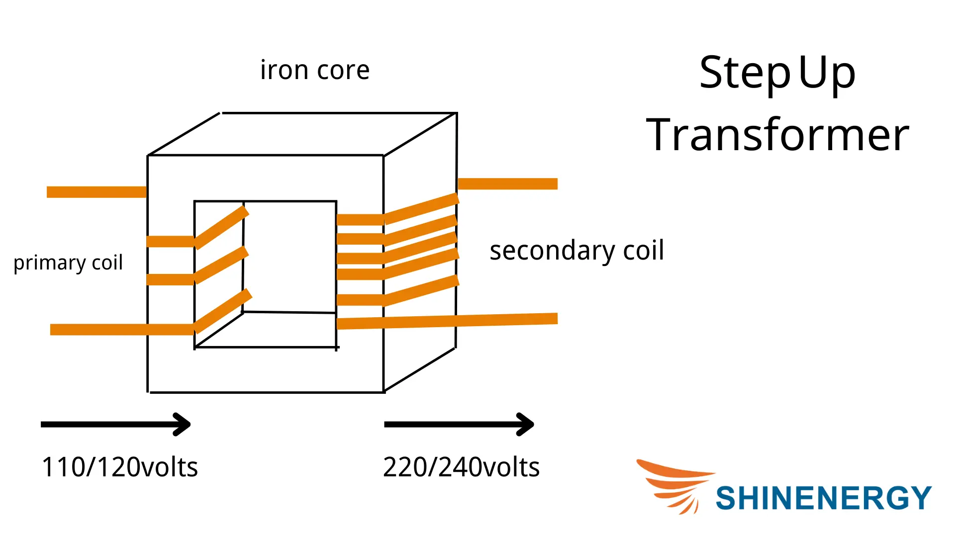
Figure 4-5 Primary secondary transformer facility
Effect of Wiring Style on Voltage and Current
The wiring method directly affects the voltage and current output of the transformers. For example, in star wiring, the line voltage is higher than the phase voltage, while in delta wiring, the line voltage is equal to the phase voltage. The wiring method also affects the load capacity and power output of the transformers. For applications where high current and low voltage output are desired, delta wiring is often chosen, while star wiring is more advantageous where high voltage transmission is required.
Case: In a building’s electrical system, an elevator drive system may use a transformer with triangular wiring for high current output.while a building lighting system may be more suited to star wiring because such systems have a high demand for high-voltage transmission but not a high power requirement.
Transformer design
Key Factors Affecting Transformer Design
When designing transformers, several factors determine its performance, efficiency, and service life. The following are a few key factors:
- Transformer Material selection: The choice of core and winding materials directly affects the transformer’s losses and efficiency. For example, the use of highly permeable silicon steel sheet can reduce magnetic losses, while high-purity copper windings can reduce resistance losses.
- Transformer Insulation: Insulation materials affect the voltage withstand and safety performance of transformers, especially in high voltage transformers where the quality of insulation is critical. The design must take into account the heat resistance and durability of the insulating material.
- Transformer Cooling design: An effective cooling system design helps to control temperature rise and prevent overheating. Different cooling methods are applicable to different types of transformers, for example, dry-type transformers are generally air-cooled, while oil-immersed transformers are oil-cooled to enhance heat dissipation.
Case in point: In outdoor high-voltage substations, oil-immersed cooling designs are often used because these devices generate a lot of heat during operation. oil cooling keeps the transformers at a stable temperature for a long time.
How to Improve Transformer Efficiency?
Transformers efficiency directly affects the cost and stability of the power system, and the following are a few design strategies to improve efficiency:
- Reducing iron and copper losses
- Optimized winding design
- Improving power factor
Case: In some industrial power equipment, switching to low-loss core materials and optimizing the winding structure can increase transformers’ efficiency by 1-2 percentage points. which can save considerable power costs in high-power equipment.
Temperature Rise Reduction and Load Management
In power distribution, transformers what do they accomplish that makes them so vital? The temperature rise of transformers not only affects their efficiency but also has a direct impact on insulation and service life, so temperature control is critical.
- Temperature rise can be effectively reduced by using good cooling systems
- Reasonable load management
- Distributed winding
Case in point: Transformers’ electrical components play a vital role in energy distribution systems. During periods of peak grid loads, utilities use load management strategies to gradually distribute loads to reduce the burden on individual transformers, extend equipment life, and reduce losses due to temperature rise.
Transformers in different industries
The Central Role of Transformers in Industry
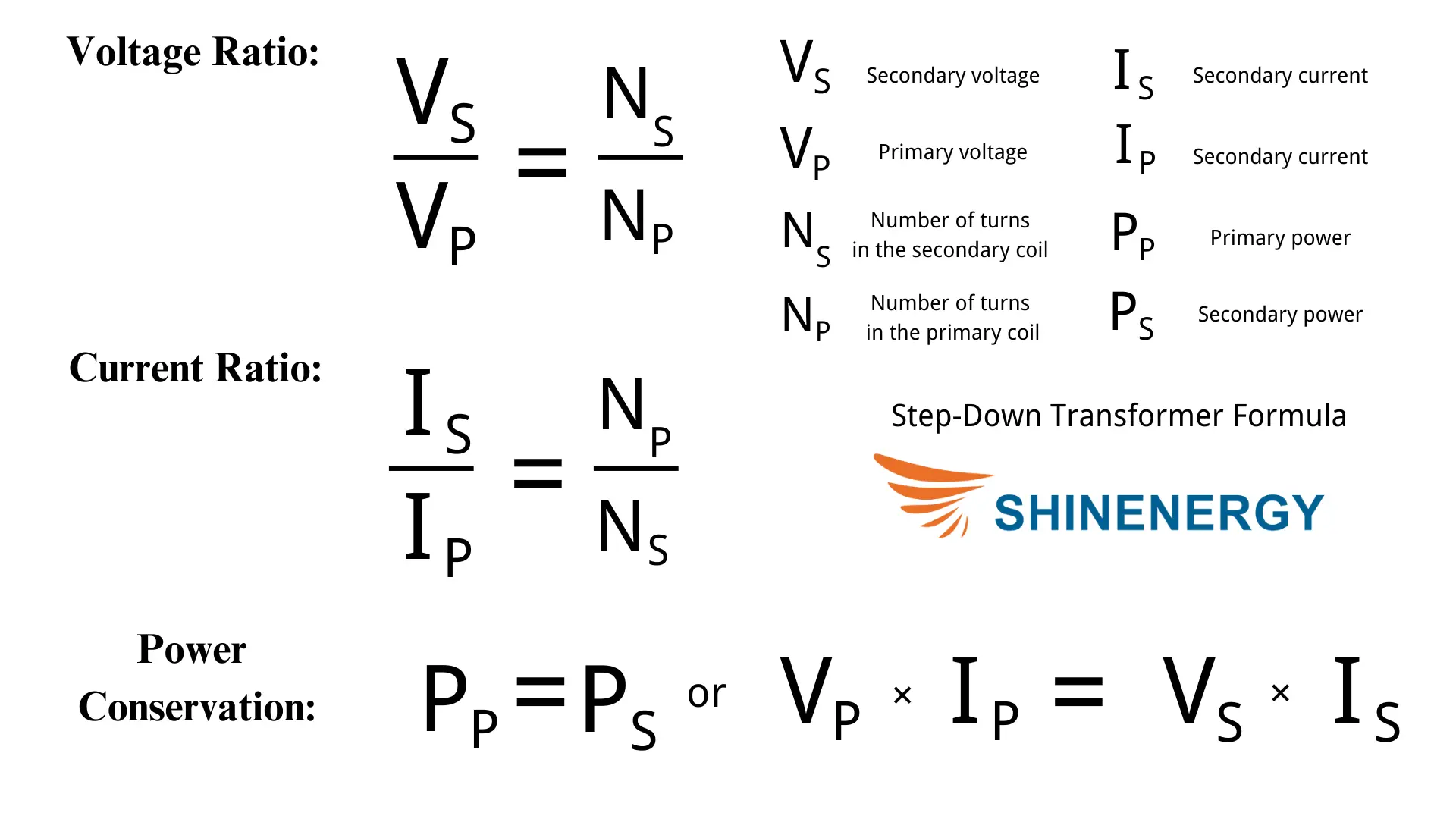
Figure 6-1 photo of electrical transformer
In the industrial sector, the central role of transformers is to support the stable operation of high-power equipment and to ensure that factories and production lines are reliably supplied with power. Transformers used in industrial environments are often subjected to high currents and voltages and are therefore designed for durability and high performance. Industrial transformers can switch between different voltage levels, allowing equipment to operate more efficiently and at lower production costs.
Transformer Applications in Renewable Energy Systems
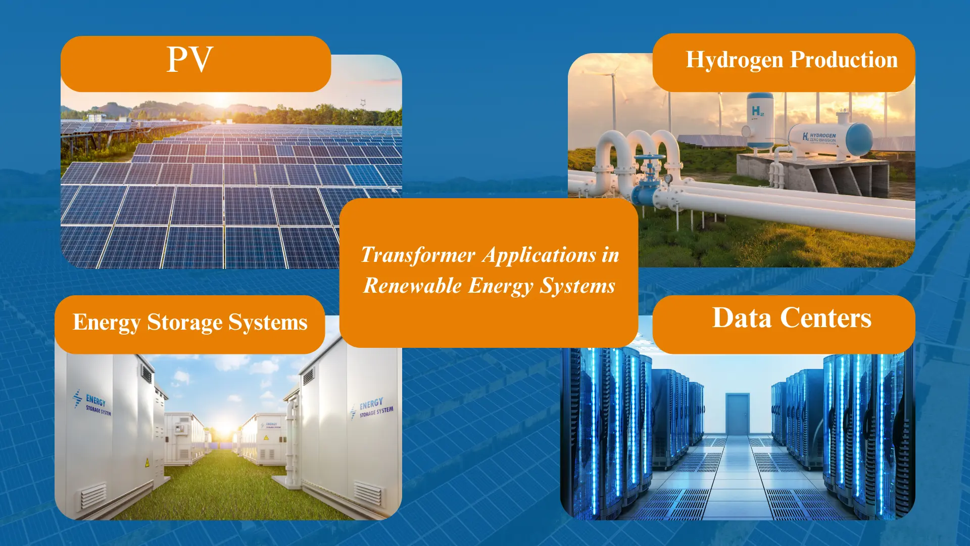
Figure 6-2 Transformer applications
The main task of transformers in these systems is to step up the low-voltage current produced by the generator to a high voltage suitable for transmission, in order to reduce losses during long-distance transmission. These transformers usually need to be corrosion and moisture resistant and adaptable to outdoor or extreme environments.
- Transformers in Energy Storage Systems
- Transformers Applications in Data Centers
- Transformers electronics are essential for safely converting power in a variety of applications.
- The Role of Transformers in Commercial and Residential Power Supply
Transformer maintenance
Regular Maintenance
- oil immersed transformers: oil quality needs to be checked regularly to ensure that the cooling oil has good insulating properties. If the oil is found to be discolored or impurities increase, it should be replaced in time. In addition, check the sealing of the oil tank to avoid oil leakage and air entry.
- Dry type transformers: Clean the surface of the transformers regularly, especially in dusty environments, to prevent dust from affecting heat dissipation. Insulation materials and windings also need to be inspected to ensure that there is no deterioration or damage caused by temperature or humidity changes.
Transformer Common Failures
- Transformers overload failure
- Transformers insulation aging
- Transformers cooling system failure
- Transformers coil short circuit
Transformer wiring guide: transformer wiring schematic
When working with transformers, it’s crucial to refer to the wiring diagram of transformers to understand the correct connections. Following the wiring diagram for transformera installation can help prevent electrical hazards and ensure proper functionality. For electricians, knowing how to interpret wiring a transformers diagram is essential, especially when dealing with power distribution systems.

Single phase 480 to 120/240 transformer wiring diagram

3 phase transformer wiring diagram

delta wye transformer diagram

delta transformer diagram

wiring a transformer diagram

phase transformer wiring schematic

wye transformer diagram

Transformer wire diagram

3 phase transformer wiring schematic
FQA
Why is it important to clarify the transformer abbreviation when documenting electrical schematics?
To avoid misunderstandings and ensure accurate interpretation by all team members. In technical drawings, using the transformer short form can save space and improve clarity.
What are standard transformer sizes?
Typical transformer sizes vary but commonly include ratings like 15 kVA, 30 kVA, 50 kVA, 75 kVA, 100 kVA, and higher, depending on application needs. The role of transformers electricity distribution is essential for managing voltage across long distances.
| 15 kVA transformer | 30 kva transformer | 75 kva transformer amps | 150 kva transformer |
| 225 kva transformer | 300 kva transformer | 50 kva transformer | 25 kva transformer |
| 2000 kva transformer | 750 kva transformer | 1000 kva transformer | 1500 kva transformer |
transformer sizing table
Why is it important to understand the difference between load vs line side?
“Understanding load vs line side is crucial for correct wiring and ensures that power flows safely and correctly through the system. Transformers electronics play a key role in converting voltage levels for different devices.”
What is the benefit of using Series-Multiple Windings (Re-Connectable Transformers)?
“Series-Multiple Windings (Re-Connectable Transformers) offer flexibility, allowing adjustments for different voltage requirements by reconfiguring the connections.”
What Energy Transformation Occurs in a Transformer
The transformers change electrical energy from one voltage level to another without altering its frequency. Transformers play a vital role in power transmission, such as the power pole transformers and power line transformers, which help regulate and maintain stable powerline voltage. Transformers on power lines convert high voltage electricity to suitable levels, ensuring safe power distribution across regions. The main power transformers typically handles higher voltage, while the transformers power line links various nodes within the transmission system.
What is a Transformer in Electricity?
The transformers are a device that transfers electrical energy between two or more circuits through electromagnetic induction. The transformers are a device that increases or decreases voltage; its main function is voltage transformation. Whether it’s an electrical outlet transformers or a battery charger transformers, each needs to adjust voltage to the appropriate level for safe device operation. Simply put, what does an electrical transformers do? It transfers electrical energy between different voltage levels through electromagnetic induction, ensuring devices can operate safely and effectively.
How Much Voltage is in a Power Line?
Power line voltage varies but typically ranges from 120 volts in homes up to hundreds of kilovolts (kV) for long-distance transmission lines. Transformers come in various forms for different applications, such as the specialized trafo toroidale or the commonly used 120v transformers. In industrial or large-scale power transmission, transformers are used to raise and lower voltages, enabling efficient power transmission across distances. Whether it’s transformesrs electricity for household use or transformers’ link in the grid, these devices play a key role in maintaining system stability.
How Does a Transformer Work Physics
The transformers works by using electromagnetic induction to transfer electrical energy between coils, altering voltage levels as needed. The three parts of a basic transformers are the essential components, such as the core and windings. Whether in an industrial niagara transformers or standard transformers in electrical systems, these components ensure effective and stable voltage conversion. The design and material choice of transformers electrical parts directly influence its performance and efficiency.
What does Step Down Transformer Do?
The step down transformers reduces high voltage to a lower, safer level suitable for household or device use.
What is a transformer and what does it do?
The transformers is a device that adjusts voltage levels. In power systems, transformers on power lines use efficient electromagnetic induction to raise or lower voltage, supporting the needs of various electrical devices and equipment.
Why is Power Conserved in Transformers?
Power is conserved in transformers because the energy transfer involves only voltage and current transformations, ideally with minimal losses.
How Much Electricity Does a High-voltage Transformer Produce?
High-voltage transformers do not produce electricity; they modify the voltage of electricity that passes through them.
How Does a Transformer Operate
The transformers operate by passing alternating current through primary coils, inducing a magnetic field that generates voltage in secondary coils.
How Long Does it Take to Fix a Transformer?
Fixing transformers can take anywhere from a few hours to several days, depending on the damage and availability of replacement parts.


Pingback: เสริมจมูกที่จีน
Pingback: business presentations
Pingback: ชุดเครื่องเสียง