Ohm’s Law and Joule’s Law play a key role in the Transformer calculation formula. These two formulas not only help us understand the relationship between current, voltage, and resistance in a circuit but also ensure the safe and efficient operation of a power transformer through transformer calculations. By mastering these basic concepts, we can not only accurately carry out the design of the transformer, but also optimize its performance, reduce losses, and improve the efficiency of power transmission. The practical application of these electrical formulas can bring great help to the daily operation of the project and ensure the stability and reliability of the system!

Figure 1 Transformer calculation formula
Ohm’s Law in Transformer Formula

Figure 1-1 Ohm’s law and formula
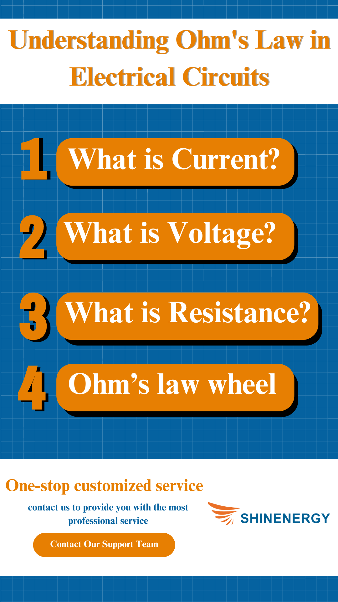
What is Current?

Figure 1-2 Ohm’s law equation
Current refers to the flow of electric charge through a conductor, typically measured in amperes (A). Imagine water flowing through a pipe – the more water (or charge) moving, the stronger the current. For example, if you connect a lightbulb to a battery, the current flows from the battery to the bulb, lighting it up.
What is Voltage?

Figure 1-3 voltage equation(formula of volts)
Voltage is the force that pushes electric charges through a circuit, measured in volts (V). Think of it like water pressure in a hose – higher pressure means faster water flow. For instance, when you plug a phone charger into an outlet, the voltage forces current through the charging cable, powering your phone. The voltage equation is a fundamental concept in electrical systems that expresses the relationship of voltage to current and resistance. According to Ohm’s law, the equation for voltage is voltage = current x resistance.
What is Resistance?

Figure 1-4 power voltage current(Resistance formula in Ohm’s law)
Resistance opposes the flow of electric current, measured in ohms (Ω). It’s like a narrow section of pipe that slows down water flow. An example is a toaster – its heating element has high resistance, which converts electrical energy into heat to toast bread. The resistance power formula expresses the relationship between resistance voltage and current with the expression R = V / I. The resistance equations help us to calculate the value of resistance from known voltage and current. The electricity resistance formula is not only used in simple circuits but can also be used to analyze complex circuits. The resistance current voltage formula enables us to evaluate the power loss and heat generation in a circuit. The resistance equation plays an important role in engineering and physics and is widely used to design and optimize electronic equipment and the safe operation of electrical systems.

Figure 1-5 Formula Ohm’s law
What is Ohm’s Law?
voltage current resistance formula:
V=IR
R=V/I

Figure 1-6 formula for volts
Ohm’s Law describes the relationship between voltage, current, and resistance in a circuit. It is given by V = I ∗ R, where V is the voltage in volts, I is the current in amperes, and R is the resistance in ohms. The law shows that in a circuit, voltage is equal to the product of current and resistance. Ohm’s law allows you to calculate current from a known voltage and resistance, or resistance from a known current and voltage and is a fundamental tool in circuit analysis.
What is the current equation for the ohms formula?
How to work out voltage? Using Ohm’s Law formulas like V=I∗R, you can calculate the voltage, current, or resistance in an electrical circuit by knowing two of the three variables. These voltage equations are fundamental for designing and troubleshooting electrical systems.
V=I∗R
“V” is the voltage (in volts)
“I” is the current (in amperes)
“R” is the resistance (in ohms)

Figure 1-7 ohms law formula
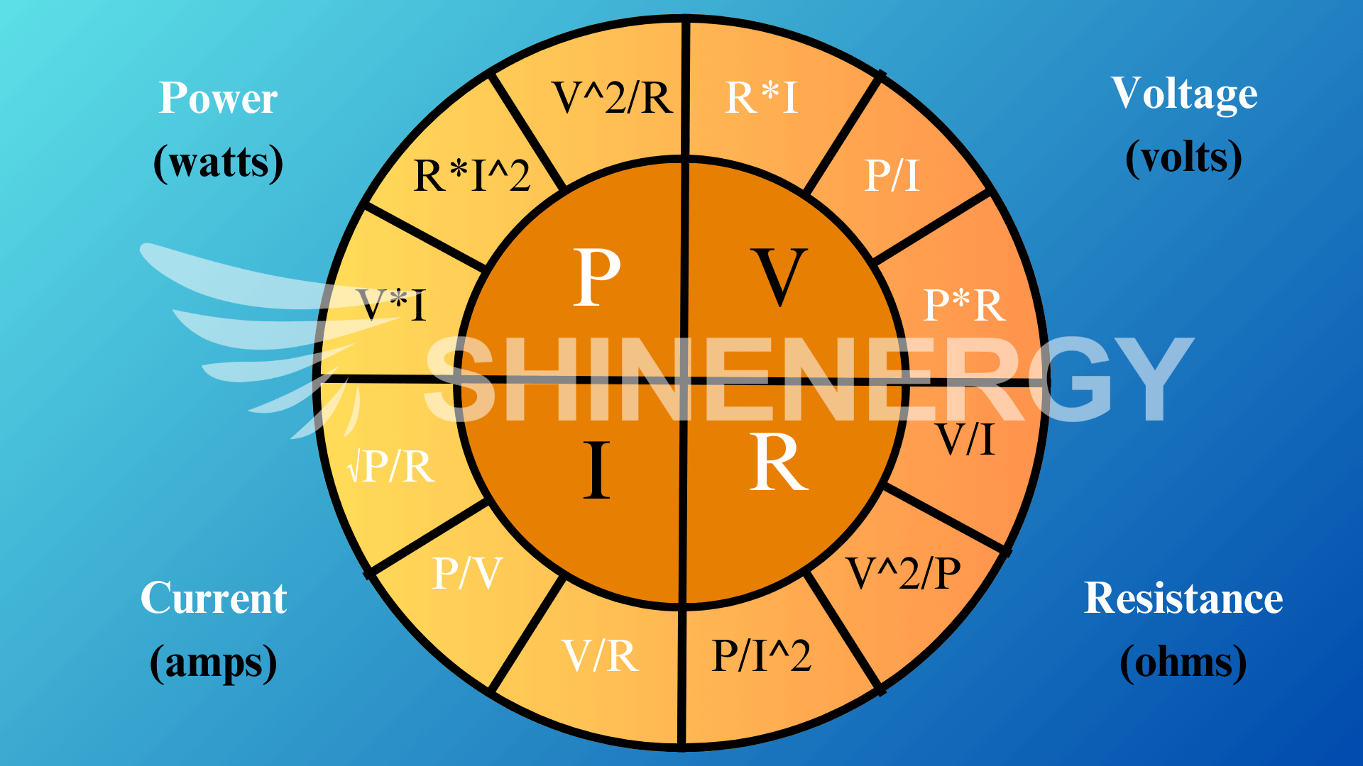
Ohm’s law wheel in Transformer Formula

Figure 1-8 ohms law wheel
Applying Ohm’s Law in Transformer Circuits – Practical Examples

Figure 2 Formula for power electrical
Scenario 1:
Transformer Formula: Calculation of voltage and current in photovoltaic applications

Figure 2-1 current i formula
Usage Scenario: Photovoltaic power generation system output 240 V, load resistance is 80 Ω. Calculate the current by Ohm’s law:
I=V/R=240V/80Ω=3A
This indicates that the PV system provides a 3A current to the load to ensure stable operation of the system and avoid equipment damage caused by excessive current.
Scenario 2:
Transformer Formula: Troubleshooting in Energy Storage Systems

Figure 2-2 What is v/i
Usage Scenario: The energy storage system outputs 120 V and the current is measured to be 6 A. Calculate the resistance by Ohm’s law:
R=V/I=120V/6A=20Ω
However, the normal resistance should be 30Ω, indicating that there may be a short circuit, which needs to be repaired.
Scenario 3:
Transformer Formula:Data Center Load Conditioning

Figure 2-3 joules a ohms
Usage Scenario: Data center load resistance 50Ω, output voltage 100V. current is calculated as:
I=V/R=100V/50Ω=2A
Adjusting the power supply according to the current ensures that the server runs efficiently without being overloaded.
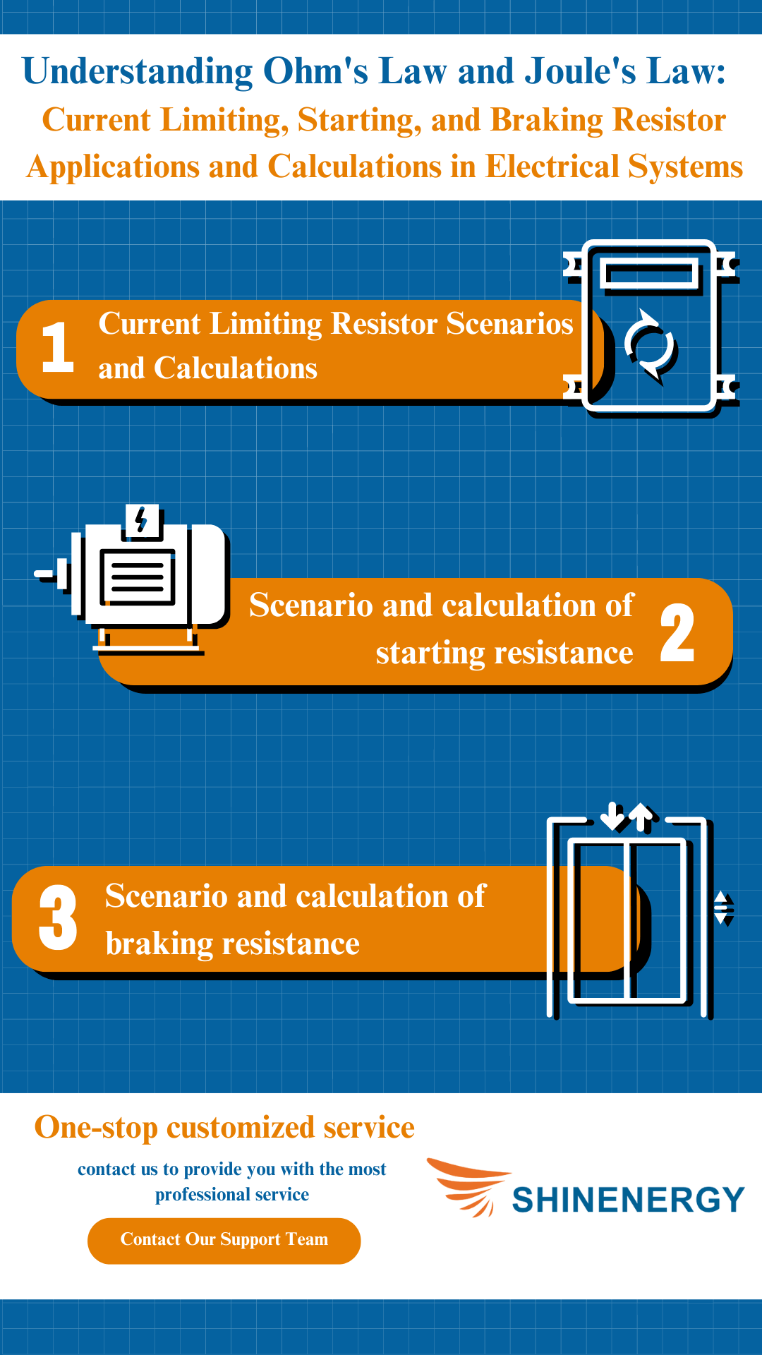
Current Limiting, Starting, and Braking Resistor Applications and Calculations in Transformer formula

Figure 3 power voltage current formula
Now, let’s apply a form of Ohm’s Law to a real-world situation with a constant value of resistance – such as a current-limiting resistor, a starting resistor, and a braking resistor. Low resistance grounding systems rely on resistors to limit the amount of fault current during a line ground fault. This is accomplished by connecting a resistor between the neutral of the transformer and the ground. Using the formula for current resistance and voltage V=I∗R, you can calculate the voltage by multiplying current and resistance, or solve for current or resistance if the other two values are known. This formula is fundamental in electrical circuit calculations.
1. Current Limiting Resistor Scenarios and Calculations
Scenario: In an industrial inverter, suppose the system operating voltage is 480V and the short circuit current is required to be limited to 50A. We can realize this by calculating the current limiting resistance
R=V/I=480V/50A=9.6Ω
2. Scenario and calculation of starting resistance
Scenario: A 3-phase induction motor, running at 400V, is currently limited to 100A at startup. The impedance of the motor is 5Ω and the starting resistance is calculated as follows:
R=V/I-R=400V/100A-5Ω=4Ω
Adding a 4Ω starting resistor can effectively limit the current during startup to avoid overloading the device.
3. Scenario and calculation of braking resistance
Scenario: Elevator system, during braking, the system voltage is 300V, and the current is required to be limited to 30A within 5 seconds. We calculate the braking resistance by the following formula:
R=V/I=300V/30V=10Ω
This 10Ω braking resistor can quickly dissipate energy when the elevator stops, ensuring safe braking.
Equation of Power Electrical: Exploring Joule’s Law in Transformer Calculation Formula

Figure 4 Electricity power calculation formula
What is Joule’s Law?

Figure 4-1 joules formula
Joule’s Law describes the relationship between the heat produced by an electrical current passing through a conductor. It states that the heat generated is proportional to the square of the current (I), the resistance (R) of the conductor, and the time (t) the current flows. Using joule a ohms together, we can calculate the heat produced in electrical circuits by the relationship between current, voltage, and resistance. The formula for Joule’s Law is:
Q=I^2∗R∗t
Joule’s law equation?

Figure 4-2 power formula electricity
Where Q is the heat energy (in joules), I is the current (in amperes), R is the resistance (in ohms), and t is the time (in seconds). Using the Joule formula Q=I^2∗R∗t, we can calculate the heat generated in a conductor over time by considering the current, resistance, and duration of current flow. This equation for power is fundamental in understanding energy dissipation in electrical circuits.
Practical application of Joule’s law in transformers?

Figure 4-3 What is the formula for power
Joule’s Law is applied in transformers primarily to calculate the heat losses due to the flow of current through the windings, known as I²R losses. In a transformer, as current passes through the windings (which have resistance), some electrical energy is converted into heat. This heat dissipation can affect the transformer’s efficiency. By using Joule’s Law ( P = I² * R ), engineers can estimate these losses and design appropriate cooling systems to maintain transformer performance and prevent overheating.
Power Equation: Combining Ohm’s and Joule’s Law in Transformer Calculation Formula

Figure 5 power formulas
Combined application of Ohm’s law and Joule’s law in the photovoltaic industry

Figure 5-1 Formula of power
In a photovoltaic power plant, a transformer converts the DC current generated by the solar panels into AC current. Assume that the transformer outputs 20A current with a resistance of 3Ω and apply Ohm’s law:
V = I * R = 20A * 3Ω = 60V
The power loss is then calculated using Joule’s law:
P=I^2∗R=20A
2∗3Ω=1200W
P = I² * R = 20A² * 3Ω = 1200W
This 1200W of heat loss requires effective thermal management to maintain system efficiency.
Combined application of Ohm’s law and Joule’s law in the energy storage industry

Figure 5-2 Formula for electrical
Using the equation voltage V=I∗R, you can determine the voltage in a circuit by multiplying the current by the resistance. This formula is key in electrical engineering for understanding circuit behavior. In an energy storage system, a transformer regulates the flow of electricity. Assuming a current of 15 A and a resistance of 4 Ω, apply Ohm’s law:
V=I∗R=15A∗4Ω=60V
Then use Joule’s law:
P = I² * R = 15A² * 4Ω = 900W
This 900W of heat loss indicates the need to optimize heat dissipation to ensure efficient operation of the energy storage system. Using the formula for voltage P=V∗I, we can calculate the electrical power by multiplying voltage and current, which is essential in determining the energy consumption in circuits.
Combined Application of Ohm’s Law and Joule’s Law in the Data Center Industry

Figure 5-3 Voltage and joules
Transformers are used in data centers to provide power to servers. Assuming a current of 25A and a resistance of 2Ω, apply Ohm’s law:
V=I∗R=25A∗2Ω=50V
Calculate power using Joule’s law:
P = I² * R = 25A² * 2Ω = 1250W
This 1250W power loss requires an effective cooling system to prevent the server from overheating and to ensure the stable operation of the data center.
Transformer Sizing and Power Factor Considerations

Figure 6 Formula power current voltage
Transformer sizing is critical to ensure that the transformer can handle the load it will supply. The size is determined based on the total power demand (in kilovolt-amperes, kVA), which is calculated by considering the apparent power needed by the load. A key factor in transformer sizing is the power factor (PF), which measures how efficiently electrical power is converted into useful work.
Apparent Power and Power Factor:

Figure 6-1 Formula voltage
The apparent power (S) in a system is calculated by:
S=V∗I
where:
“V” is the voltage
“I” is the current
However, this is only part of the story. The real power (P) that does actual work is influenced by the power factor (PF), calculated by:
P=V∗I∗PF
A low power factor indicates that the system has a large reactive load (like motors or inductive loads), which can increase losses and require a larger transformer. For example, if the system has a 0.8 power factor, it will require a larger transformer to compensate for inefficiencies compared to a system with a 0.95 power factor.
Transformer Sizing Example

Figure 6-2 volt formula
In a data center, where the total load is 200kW with a power factor of 0.9, the required transformer size (apparent power) is:
S=P/PF=200kW=222.2kVA
In this case, you would select a transformer with a capacity of at least 225kVA to handle the load safely.
Example 1: Solar Energy Storage System
In a photovoltaic and energy storage system, suppose the total power is 150kW with a power factor of 0.85, The required transformer size is:
S=P/PF=150kW/0.85=176.5kW
Here, you would need a transformer0.85 with a minimum capacity of 180kVA to handle the load.
Example 2: Data Center
For a data center with a 300kW load and a power factor of0.95:
S=P/PF=300kW=315.8kVA
A transformer of at least 320kVA is recommended for optimal performance.
Power Factor Correction:
 Figure 6-3 volt formula
To improve efficiency, power factor correction can be applied. This reduces the reactive power in the system, allowing the transformer to operate closer to its rated capacity. Capacitors or other power factor correction devices are typically used to bring the power factor closer to 1, thus optimizing transformer usage and reducing the overall required size. Understanding transformer sizing and managing power factors is crucial for ensuring efficient and reliable system performance, especially in industries like data centers, where uninterrupted power is essential.
What is the power factor?

Figure 6-4 power formula
Power factor (PF) is the ratio of real power (P) that does useful work to the apparent power (S) in an electrical system. It is a measure of how efficiently electrical power is being used. The formula for the power factor is:
PF=P/S
A power factor of 1 (or 100%) indicates that all the power is being used effectively. A lower power factor means that some energy is wasted in the form of reactive power, which doesn’t do useful work but affects the load on the system.
What is the equation for power electrical?

Figure 6-5 Calculation transformer
Using the Watts Law formula P=V∗I, you can calculate the power in watts by multiplying voltage and current. This formula is essential for determining the power consumption in electrical circuits and is commonly used in electrical engineering and power management.
P=V∗I
“P” is the power (in watts)
“V” is the voltage (in volts)
“I” is the current (in amperes)
This formula calculates the real power consumed in an electrical circuit. If the power factor is involved in AC circuits, the equation becomes:
P=V∗I∗PF
Using the 480 voltage power and current formula, P=V∗IP = V * IP=V∗I, we can calculate the power in a circuit with a voltage of 480V by multiplying it with the current (I). This formula is essential for determining the electrical load and power requirements in various systems.
Summarizing Key Formulas and Their Impact on Transformer Design

Figure 7 Formula for ohms
Ohm’s Law helps calculate voltage, current, and resistance, crucial for determining load behavior. Joule’s Law calculates heat loss due to resistance, impacting transformer efficiency and cooling needs. Apparent Power calculates the required transformer capacity, factoring in the power factor to size the transformer appropriately. If you need more information or have any questions, please feel free to contact our team. We will be happy to provide you with detailed help and support to ensure that your needs are responded to in a timely manner.
FAQ
What is the transformer equation?
Variable pressure ratio formula
V1/V2=N1/N2, Used to calculate primary and secondary voltages as a function of the number of turns in a coil
Power formula
P=V*I, Used to calculate power, voltage multiplied by the current is power.
Ohm’s law
V=I*R, Used to calculate the relationship between voltage, current, and resistance
How to Calculate Transformer Size Calculator
To calculate transformer size using a transformer sizing calculator, you typically input key values such as load power (in kW or kVA), voltage (primary and secondary), current, and power factor. The calculator will then compute the appropriate transformer size (in kVA) to meet the load requirements, ensuring the transformer is neither under-sized nor over-sized. Using transformer calculations, you can determine the appropriate transformer size and performance based on factors such as input/output voltage, current, and power load. These calculations help optimize transformer design for efficiency and safety.
What is the three phase transformer calculation formula for determining voltage and current relationships in a transformer system?
What are the electrical engineering basic formulas used to calculate voltage, current, power, and resistance in circuits?
- Ohm’s Law: V=I∗R (Voltage, Current, Resistance)
- Power Formula: P=V∗I (Power, Voltage, Current)
- Watts Law: P=I2∗Ror P=V2/R (Power, Current, Resistance)
- Kirchhoff’s Voltage Law (KVL): The sum of voltages in a closed loop equals zero.
- Kirchhoff’s Current Law (KCL): The sum of currents entering a junction equals the sum of currents leaving it.
How to calculate transformer load capacity?
- Determine the total load in kilowatts (kW) or kilovolt-amperes (kVA).
- Convert to transformer capacity in kVA. Ensure that the calculated kVA is within the transformer’s rated capacio avoid overload.

