Wiring a transformer may sound complicated, but it’s not as hard as you think once you have the basics. Whether it’s a small transformer in a home appliance or a large piece of equipment in industry, properly wiring the transformer is key to safety and proper operation. This guide will walk you through the basics of transformers, how to read wiring diagrams, and specific wiring procedures. We’ll explain it in a simple and easy-to-understand way to help you get started. Just follow the steps and you too can become a wiring expert!

Figure 1 how to wire a transformer
Basic Concepts of Transformer Wiring

Figure 1-1 series electrical wiring
Parallel vs Series Wiring

Figure 1-2 wiring in series vs parallel
When it comes to transformer wiring, you may often hear the words “parallel” and “series“. In fact, the difference between them is very simple: parallel wiring is like connecting multiple sockets together at home, each socket has its own power supply and will not affect each other; while series wiring is more like stringing batteries one by one, and the voltage will be superimposed. In other words, the series connection is mainly used to increase voltage, while a parallel connection can make the current more stable. Just choose different wiring methods according to your goals.
Series Wiring

Figure 1-3 series wiring
Series wiring is to connect multiple coils end to end so that current can flow from one coil and pass through the other coils in turn. The advantage of a series connection is that the voltage will be added, which is particularly suitable for applications where the voltage needs to be increased. For example, some of the light bulbs you use in your home are connected together in series so that the voltage can be distributed to each bulb. However, it should be noted that the current is the same in the case of a series connection, so if one component is broken, the entire system may be affected.
Parallel Wiring

Figure 1-4 wiring in parallel
Parallel wiring is like providing an independent power source for each appliance. No matter what happens to one appliance, the others can still work as usual. In the transformer, the advantage of parallel wiring is that it allows multiple devices to obtain current at the same time, which is suitable for occasions where the current needs to be stable. For example, when multiple devices need to be powered at the same time, everyone can share the load without interfering with each other. This method is like each socket in our home. You plug in a mobile phone charger and a desk lamp. They work separately, and one will not turn off the other because of a problem.
When to Use Series Connection and When to Use Parallel Connection?

Figure 1-5 wiring series and parallel
In fact, whether to choose a series or parallel connection mainly depends on whether you need to increase the voltage or distribute the current.
Series and Parallel Wiring: When using series wiring, the current flows through each device in turn, making it ideal for situations where increasing voltage is necessary. On the other hand, parallel wiring allows multiple devices to operate simultaneously, with the current divided among them, providing stability in the current distribution. The choice between series and parallel wiring depends on whether you need to boost voltage or ensure stable current for multiple devices working together.
If you want the output voltage to be higher, then choose a series connection; if you want multiple devices to work at the same time and the current to be stable, then use the parallel connection. Of course, these two wiring methods are often used in combination with actual applications, which can better meet the needs of different scenarios.
How to Read The Transformer Wiring Diagram

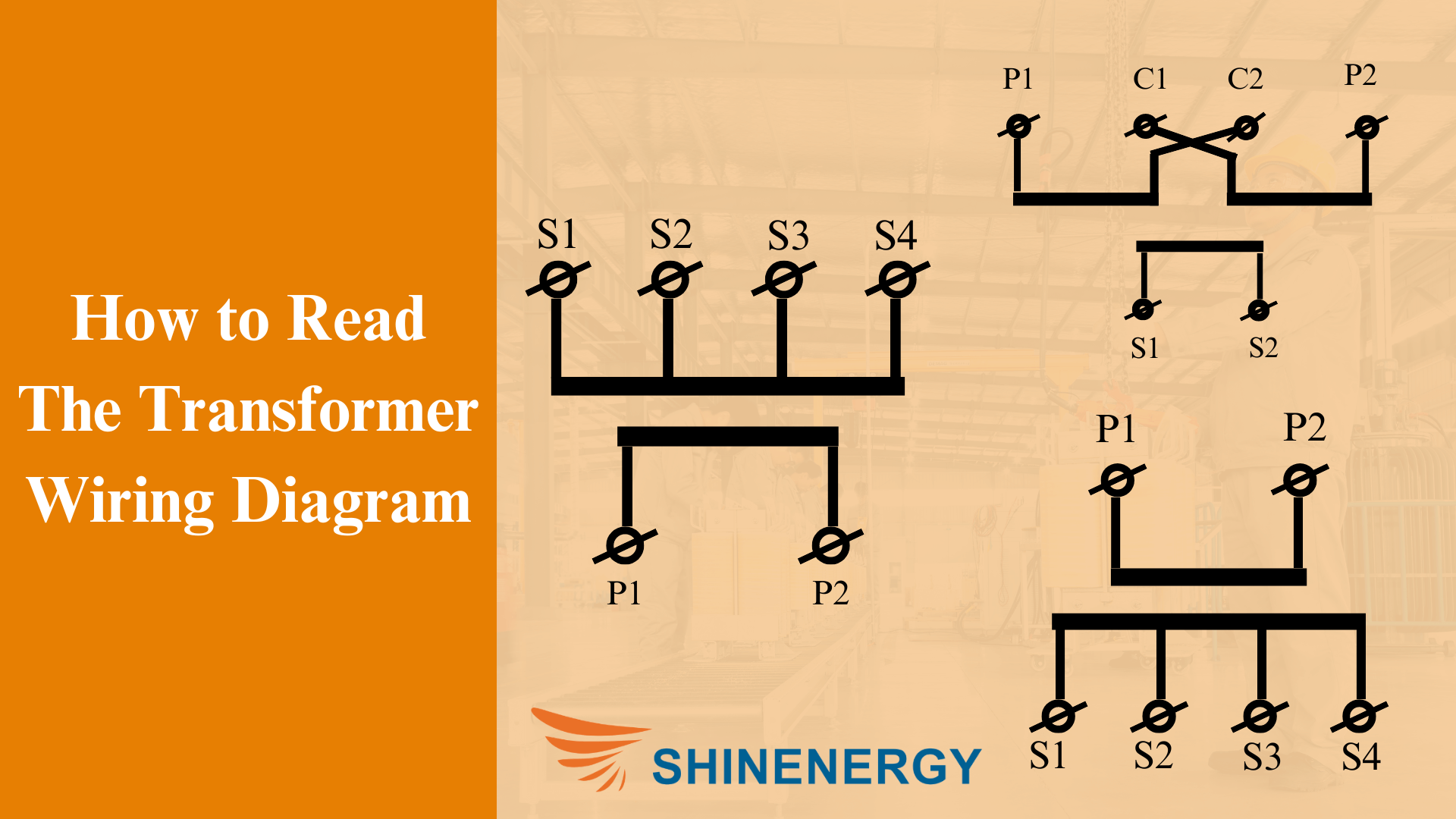
Figure 2-1 wiring diagram of transformer
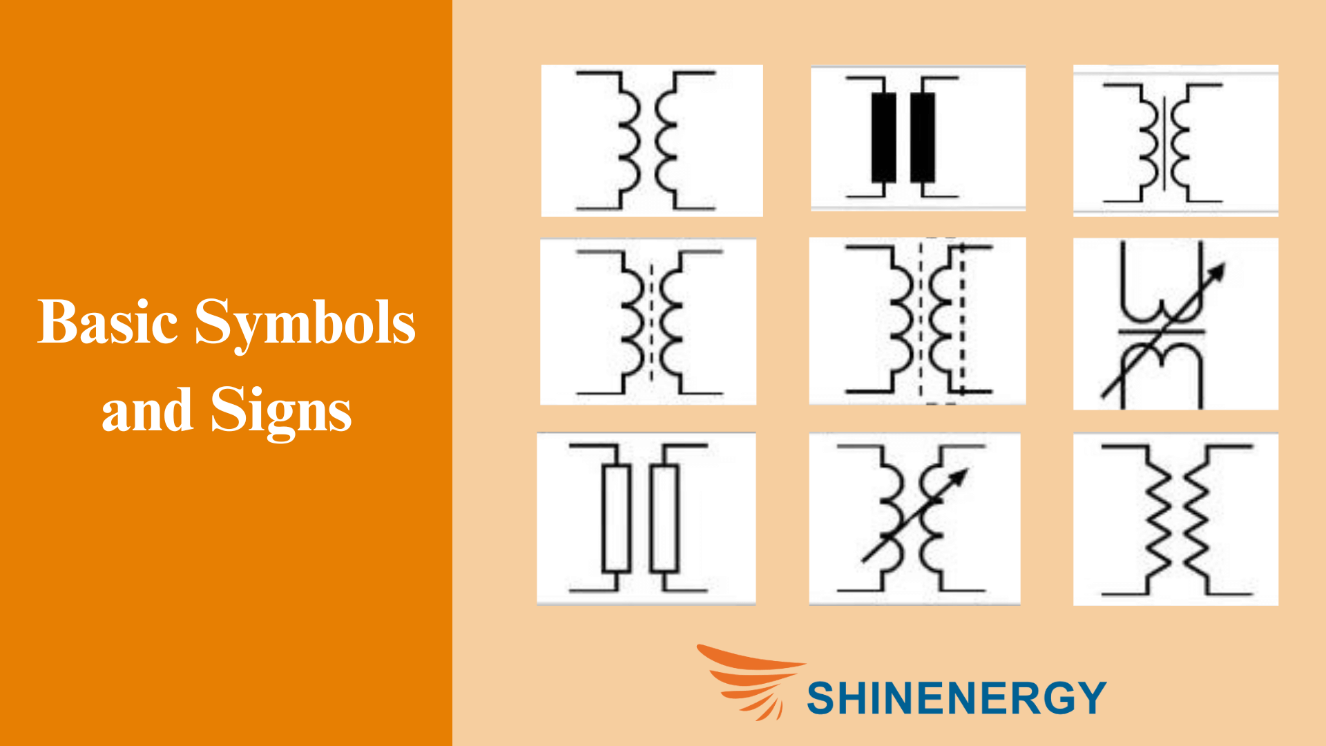
Basic Symbols and Signs

Figure 2-2 Transformer circuit
Wiring diagrams are like maps of electrical devices, and each symbol has its own meaning. Usually, there will be various small symbols on the diagram, such as coils, terminals, ground symbols, etc. The most common symbol is two wavy lines, which are coils, representing the windings of the transformer. In addition, you will see some small circles or letters that indicate different terminals, such as “P” for primary windings and “S” for secondary windings. If you remember these basic symbols, it will be much easier to read the diagram.
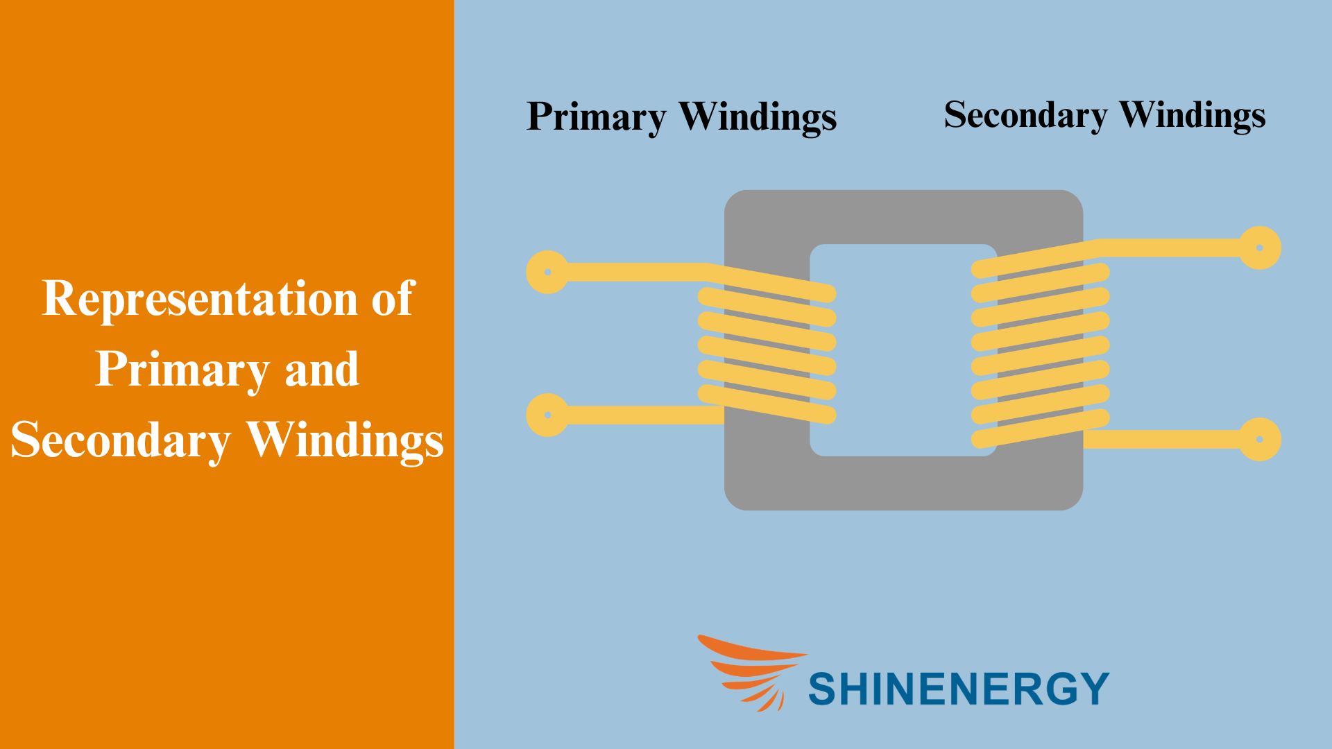
Representation of Primary and Secondary Windings

Figure 2-3 wire parallel
In wiring diagrams, the primary and secondary windings are usually distinguished by different symbols or labels. The primary winding is the part that connects to the power supply, and it is usually shown on the left or top of the diagram, while the secondary winding is the part that outputs the voltage and is usually on the right or bottom of the diagram. The drawing may have “P1” and “P2” to represent the two terminals of the primary, and “S1” and “S2” to represent the secondary terminals. You just need to connect the wires to the right positions according to the markings on the diagram.
How to Express Parallel and Series Connection

Figure 2-4 wired in series vs parallel
It’s not hard to tell wiring in parallel and series connections from a wiring diagram. The symbol for series connections is usually a coil connected end to end, like a straight line running through it; for parallel connections, you’ll see two parallel lines connecting different windings. When you see these graphics, you’ll know how to wire. If you want to increase the voltage, look for the series symbol when you look at the wiring diagram; if you want to stabilize the current, look for the parallel symbol.
Example Analysis

Figure 2-5 Transformer wire
To make it easier to understand, we can use a simple example to illustrate. For example, you get a wiring diagram of a transformer with two windings, each with two terminals, marked “P1”, “P2” and “S1”, “S2”. If the two windings in the diagram are connected in series, you will see that “P2” is connected to the other terminal of “P1”, so that the current can pass through the two windings in turn. If they are connected in parallel, you will see two sets of coils in parallel, and the current passes through them separately and then merges together. At this time, as long as you connect the wires according to the connection method in the diagram, you will not make mistakes.
In this way, understanding the wiring diagram of the transformer is no longer such a complicated matter. Through these steps, I believe you will be able to understand the wiring diagram quickly and be more confident in the actual wiring. Just like assembling furniture, just follow the drawings step by step, and you will be able to get it done soon!
Transformer Wiring: Tools and Safety Precautions

Figure 3-1 wire in series or parallel
Common Tools

Figure 3-2 Transformer wire diagram
Tools are your good helpers when wiring. First of all, you definitely need a screwdriver to tighten or loosen the terminal. Secondly, wire strippers are indispensable, which can help you easily remove the outer sheath of the wire to expose the copper wire inside, making it easier to connect the wires. And then there is a multimeter, which is very useful. It can help you check the voltage and current to ensure that the wiring is correct. If conditions permit, prepare an electrical tape and wrap it after connecting the wires to prevent short circuits and leakage.
Preparation Before Wiring

Figure 3-3 wiring diagram for transformer
Before you start wiring, remember to confirm one very important thing: Make sure to turn off the power! Whether you are connecting a small transformer for home use or a large transformer for industrial equipment, safety is always the first priority. After cutting off the power, you can also use a multimeter to check again to make sure there is no residual current. When wiring, try to operate in a dry and tidy environment. Moisture or debris may affect the safety of the wiring.
Precautions When Wiring

Figure 3-4 Parallel circuit wiring
Be especially careful when wiring to ensure that each wire is connected to the correct terminal. Especially when connecting the primary and secondary windings, do not mix them up. Also, the wire ends must be tightened, otherwise, when the current passes through, the loose connection may cause heating or even cause a malfunction. In addition, the grounding wire cannot be ignored. Proper grounding can avoid safety problems such as electric shock. If you are not familiar with grounding, you can ask an experienced electrician friend for advice.
Check After Wiring

Figure 3-5 series wire
After the wiring is completed, don’t rush to turn on the power. You need to use a multimeter or other detection tools to carefully check each contact to ensure that there is no short circuit or missing connection. If everything is fine, then carefully turn on the power to see if the device can work properly. Do not touch the wires directly with your hands to avoid the risk of electric shock. Remember, safety always comes first!
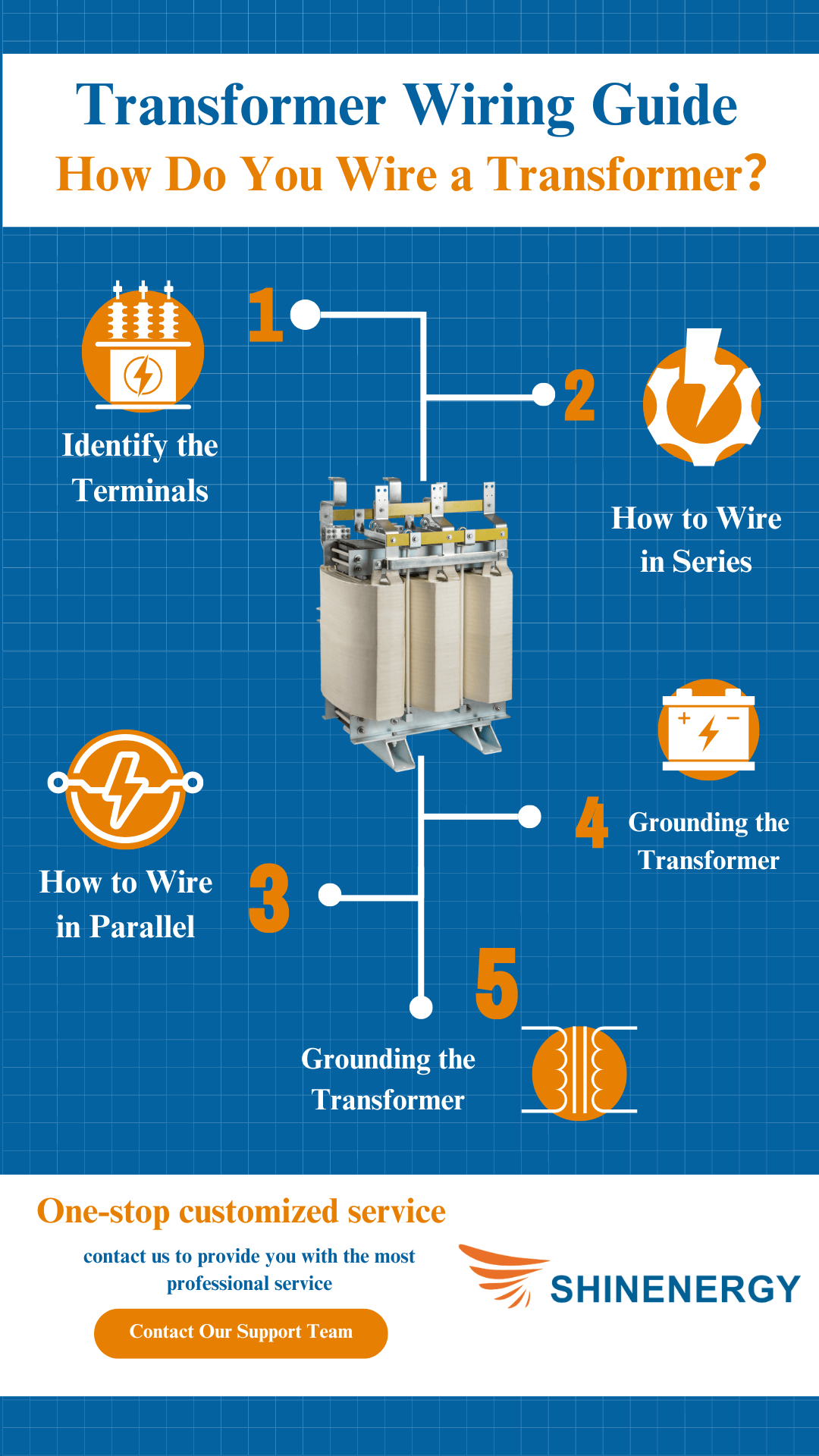
Transformer Wiring Guide

Figure 4-1 wiring a transformer diagram
Step 1: Identify the Terminals

Figure 4-2 transformer wiring schematic
Before wiring, the first step is to figure out which is the primary terminal and which is the secondary terminal. Usually, there will be clear markings on the wiring diagram, such as “P1” and “P2” to represent the two terminals of the primary winding and the secondary terminals may be marked as “S1” and “S2”. The primary terminal is the part connected to the power supply, and the secondary terminal is the part connected to the load. If it is a parallel or series wiring method, you also need to carefully look at the connection method between the terminals. In actual operation, you can use different colored wires or labels to mark to avoid the wrong connection.
Step 2: How to Wire in Series

Figure 4-3 how to wire series circuit
If you’re trying to increase voltage by connecting the components in series, here’s a tip. Series connection means that the current flows through multiple windings in sequence. To do this, you connect the “P2” terminal of the first winding to the “P1” terminal of the second winding so that the voltages add up. Remember to check the wiring diagram to make sure you’re connecting them in the right direction! Series connection is often used when you need to increase the output voltage. Remember that the voltages of each winding are added together, so make sure you don’t exceed the rated voltage of the device.
Step 3: How to Wire in Parallel

Figure 4-4 parallel electrical wiring diagram
If you want to connect the wires in parallel to increase the current capacity, the operation is actually not complicated. Parallel wiring is like letting multiple windings “share” the work at the same time. Specifically, it is to connect the “P1” of each winding together, and all the “P2” are also connected together. The advantage of this connection method is that the current can be larger, and the current borne by each winding will be evenly distributed, which is more suitable for occasions where multiple loads are used together. However, the voltage of parallel wiring will not be superimposed, so you need to make sure that the input and output voltages are consistent.
Step 4: Grounding the Transformer

Figure 4-5 Transformer grounding and bonding diagram
Grounding is a very important part that is easily overlooked. The main function of grounding is to prevent danger caused by leakage. Proper grounding can provide a safe outlet for excess current, avoiding electric shock and equipment damage. On the wiring diagram, grounding is generally marked with a symbol similar to a triangle. When operating, connect the ground wire to the metal casing of the transformer or a dedicated grounding terminal. If you are not sure how to connect, it is best to consult a professional electrician, because poor grounding can cause serious safety hazards.
Step 5: Test the Connection

Figure 4-6 wiring in parallel diagram
After connecting the wires, don’t rush to turn on the power! You need to check the entire system with a multimeter first. The first step is to test the conductivity to make sure there is no open circuit or short circuit. Then measure the voltage to make sure that the input and output voltages meet the requirements. The multimeter can help you quickly determine whether the wiring is correct. If the test results are normal, you can carefully turn on the power to see if the device works properly. But remember, do not touch the wires directly with your hands after the power is turned on to prevent electric shock.
Transformer Wiring: Common Wiring Configurations

Figure 5-1 series wiring vs parallel wiring
Overview of Common wiring Configurations (such as delta and star)

Figure 5-2 wiring transformer
In transformer wiring, the two most common configurations are delta connection (Delta connection) and star connection (Wye connection). The names may sound a bit strange, but in fact their principles are very simple.
What is Delta Connection?

Figure 5-3 wire in parallel
Delta connection (Δ connection): As the name implies, the connection is shaped like a triangle. The terminals of each winding are connected end to end to form a closed loop. The advantage of this connection is that it can withstand large currents and is often used in situations where high power output is required, such as some industrial equipment.
What is Star Connection?

Figure 5-4 Transformer connections
Star connection (Y connection): Star connection connects one end of each winding together, forming a “star” shape. Its characteristic is that the output voltage is relatively stable, which is suitable for applications that require precise voltage control, such as power supply systems in offices or some precision equipment.
How do you select the appropriate wiring configuration for a specific transformer application?

Figure 5-5 wired parallel vs series
So the question is, how to choose the most suitable wiring method for your transformer? In fact, it depends on what you need to achieve.
If your equipment requires a high current, such as some high-power motors or industrial equipment, delta wiring is a good choice. Because its closed-loop structure can withstand large currents and is relatively stable.
If your application requires stable voltage, star wiring may be more suitable. Especially in some equipment that is sensitive to voltage fluctuations, star wiring can provide a more balanced voltage output, making the equipment work more stable.
Troubleshooting of Transformer Wiring

Figure 6-1 transformer electrical circuit
Common Wiring Errors

Figure 6-2 Wiring series parallel
The most common problem during wiring is connecting the wrong wires, causing the device to not work properly. For example, the primary and secondary windings are connected in reverse, or the parallel and series connections are connected incorrectly. In this case, the transformer either does not work or the output voltage and current are incorrect. If you find that the device does not work after wiring, the first step is to check the wiring diagram to make sure that each wire is connected to the correct position. Don’t forget to mark the wires with different colors or labels to avoid cable confusion.
Voltage or Current Mismatch

Figure 6-3 wiring diagram transformer
Sometimes, after the transformer is connected, the output voltage or current is not correct. This is usually caused by the wiring configuration not meeting the requirements. For example, if you need to increase the voltage, and you choose parallel wiring, the voltage does not change. At this time, you need to recheck the wiring method and make sure to choose the series or parallel configuration according to your needs. If there is still a problem, you may need to check whether the windings are connected correctly again.
Short Circuit and Open Circuit Problems

Figure 6-4 how to wire series
Short circuits and open circuits are among the most common faults when wiring a transformer. If the wiring is too loose or a certain point is in poor contact, it may cause an open circuit and the transformer will not work at all. A short circuit may be caused by accidental contact between wires, which prevents the current from flowing normally and may even cause heating or burn the equipment. Therefore, after wiring, be sure to check the conductivity with a multimeter to ensure that there is no short circuit or open circuit.
Overheating or Buzzing

Figure 6-5 wire in series vs parallel
If the transformer overheats or hums when it is working after the wiring is completed, it is most likely caused by improper wiring. Overheating usually means that the current is too large, which may be caused by improper wiring or mismatched windings. The hum is usually the resonance of the iron core inside the transformer, which may be caused by loose wiring. The solution to this problem is to recheck the wiring and make sure that each connection is firm and that the power and current load of the equipment do not exceed the rating of the transformer.
How to Solve the Problem

Figure 6-6 wiring in parallel or series
Once a fault is discovered, the first step to solve the problem is to shut off the power to ensure safety. Then check each wiring point step by step, using a multimeter to test the voltage, current, and continuity. Check the wiring diagram to see if there is any wrong connection. If necessary, you can rewire. If the problem persists, you may need to check the internal windings of the equipment or consult a professional electrician to avoid unnecessary damage.
FAQ
How to Hook up a Transformer?

Figure 7-1 how to wire a transformer
To wire a transformer, first determine the type of transformer you have and the required wiring method (such as series or parallel). Then turn off the power and connect each terminal step by step according to the wiring diagram. Next, make sure all connections are tight and properly grounded. Finally, test it with a multimeter to confirm that there are no problems before powering it on for trial operation.
What Does “xfmr meaning” Stand for in Electrical Terminology?
In electrical terminology, “XFMR” stands for “transformer.”
What Does a Transformer Look Like?
Transformers are usually rectangular or cylindrical in shape, with a metal shell that contains windings and a core. The windings are usually made of copper or aluminum wire, while the core is made of stacked silicon steel sheets. On the transformer shell, you will see electrical terminals for connecting input and output circuits. The specific design of the appearance will vary depending on its voltage level and application scenario.
Which Side of a Transformer is the Primary?
In a transformer, the primary side is the side that is connected to the input power source, which receives the power and converts the voltage on the secondary side. Usually, the primary side will be marked, but the specific marking method may vary from manufacturer to manufacturer.
How Do You Wire a Single Phase Transformer With a 240V/120V Secondary to an Electrical Panelboard?
- Turn off Power: Ensure all power sources are off to avoid electrical hazards.
- Mount Transformer: Securely mount the transformer near the panelboard.
- Primary Connection: Connect the primary wires of the transformer to your power supply’s appropriate voltage lines.
- Ground the Transformer: Attach the transformer’s grounding wire to the panelboard’s grounding bar.
- Secondary Connection: Connect the secondary side wires—two ‘hot’ wires and one ‘neutral’—to the corresponding bus bars in the panelboard.
- Test the Connections: Once all connections are made, turn on the power and test the output with a voltage tester to ensure proper operation.
How to Wire a Step Down Transformer?
If your transformer is within the range of this table, you can follow our steps to connect it.
| Step Down Three Phase 480 to 240 Transformer | Step Down Three Phase 480 to 208 Transformer | Step Down Three Phase 480/220 Transformer | Step Down Three Phase 480 to 230 Transformer |
| Step Down Three Phase 480 to 400 volt Transformer | Step Down 480v to 230v 3 phase Transformer | Step Down Single Phase 480 to 208 Transformer | Step Down Single Phase 480v to 240v Transforme |
| Step Down Single Phase 480v to 400v transformer | Single Phase Step Down Transformer 480 to 208 |
- Safety Check: Turn off the power before starting, and wear insulating gloves and goggles to ensure safety.
- Select the transformer: Choose a step-down transformer that can reduce the voltage from 480V to 120V and meet the load requirements.
- Install the transformer: Install the transformer firmly in a safe and dry place close to the power supply and load.
- Wiring the primary side: Connect the 480V power supply to the H1 and H2 primary terminals of the transformer.
- Grounding: Connect the transformer grounding terminal to the grounding system for safety.
- Wiring the secondary side: Connect the secondary terminals X1 and X2 to the load and ensure that the connection is secure.
- Check the connection: Check that all connections are correct and ensure that there is no short circuit.
- Test: After connecting the wires, power on and test the secondary side output with a multimeter to ensure that the voltage is correct.
- Complete the setup: Cover all terminal boxes and ensure that the labels are clear for enhanced safety and easy future maintenance.
How to Wire a Step up Transformer?
If your transformer is within the range of this table, you can follow our steps to connect it.
| Three Phase Step Up Transformer 110v to 220v | Three Phase 120v to 240v Step Up Transformer | Three Phase 240v to 480v Step Up Transformer |
| Three Phase Step Up 277 480 Transformer | Three Phase 120 to 480 Step Up Transformer | Step Up Transformer 208 to 240 3 Phase |
| Step Up Transformer 220v to 440v 3 phase | Step Up Transformer 220v to 380v 3 phase | Step Up Transformer 240v to 600v 3 phase |
- Safety check: Make sure all power is disconnected before operation, and wear insulating gloves and goggles.
- Transformer selection: Select a step-up transformer that can increase the low voltage to the required voltage, and ensure that it meets the power requirements of the expected load.
- Installation location: Install the transformer firmly in a ventilated, dry place close to the power supply and load.
- Wiring the primary side: Connect the lower voltage source to the primary side terminals of the transformer.
- Grounding: Properly ground the transformer to prevent electric shock and electrical faults.
- Wiring the secondary side: Connect the secondary side terminals to the load that requires a higher voltage, and ensure that the connection is firm and safe.
- Check the wiring: Check all wire connections again to ensure that there are no errors or looseness.
- Voltage test: Use a multimeter to detect the secondary side output voltage after power is turned on to confirm whether the boosting effect meets the requirements.
- Completion confirmation: Make sure all terminal boxes are closed and clearly marked for future maintenance and repair.


Pingback: ตรายางออนไลน์