Many control transformer manufacturers are dedicated to producing high-quality, reliable transformers to meet the needs of different applications. From factory automation to building management, these transformers are an important part of ensuring system efficiency and safety. Understanding control transformers and how they work can help you better choose the right product for your needs.
what is a control transformer?
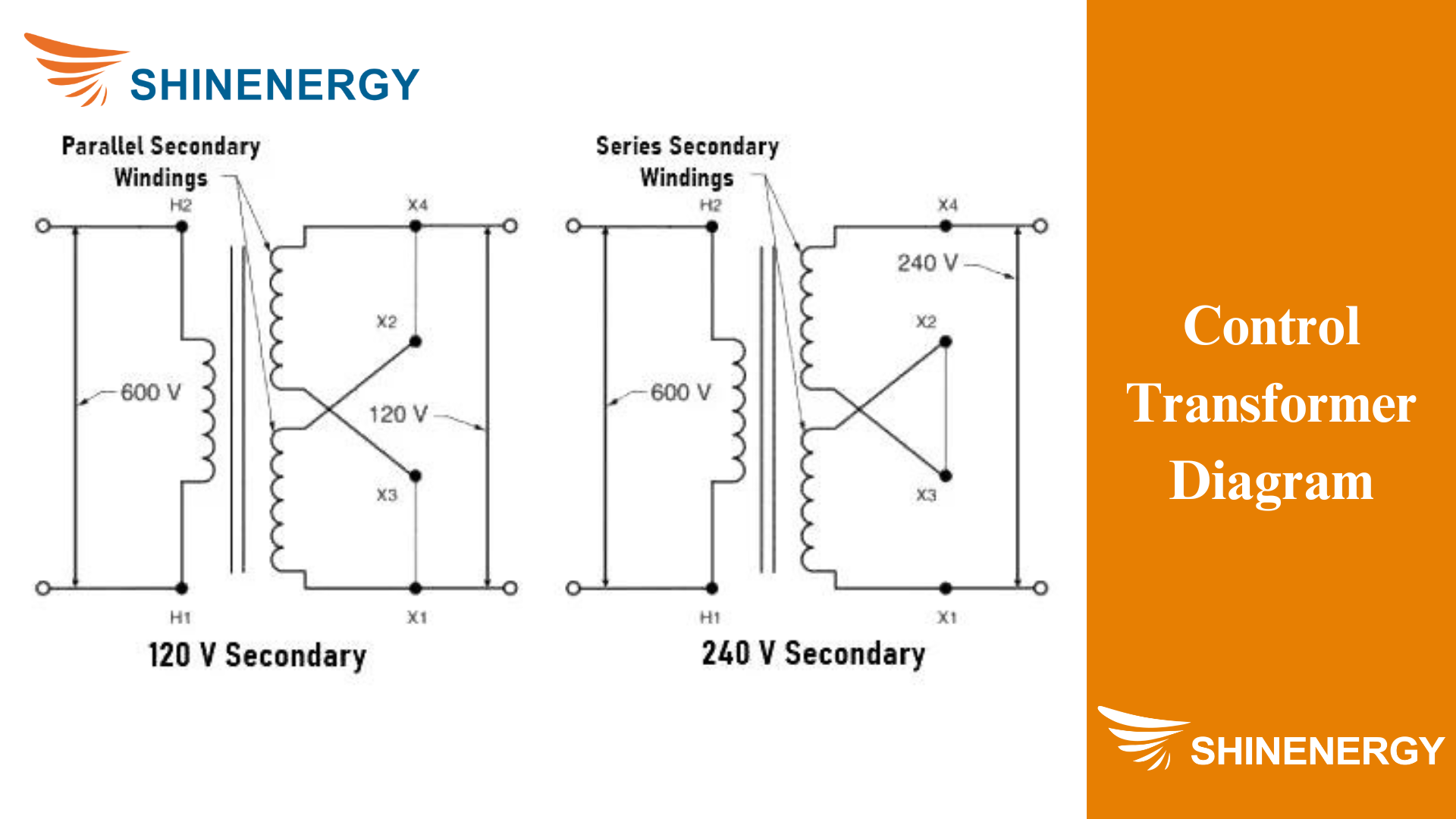
Figure 1-1 control transformer diagram
Control Transformer Definition
A control transformer is a special type of transformer designed to provide stable, low-voltage power to control circuits and devices. Think of it as a reliable power source for things like industrial control panels, automation systems, and electrical instruments. These transformers are crucial because they ensure that the control circuits receive the right amount of voltage. They protect sensitive components from electrical surges and fluctuations. In other words, control transformers help maintain the smooth operation of your control systems by delivering consistent and safe power. Plus, they filter out electrical noise, keeping your equipment running accurately and efficiently.
What Does Control Transformers Do ?: Control Transformer Working Principle
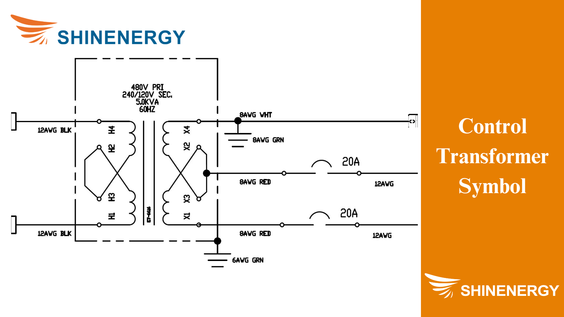
Figure 1-2 control transformer symbol
Control transformers play a crucial role in electrical systems. Control transformers are used to provide stable, low-voltage power to control circuits, which is essential for the smooth operation of industrial machinery, automation systems, and various electrical devices. Without them, your control circuits might get too much voltage, which could damage sensitive components. They also help filter out electrical noise, which means your equipment runs more accurately and efficiently. Imagine trying to operate complex machinery without a reliable power source—things could go wrong quickly. Control transformers ensure that doesn’t happen by delivering consistent power, protecting your equipment, and keeping everything running smoothly.
Type of control transformers
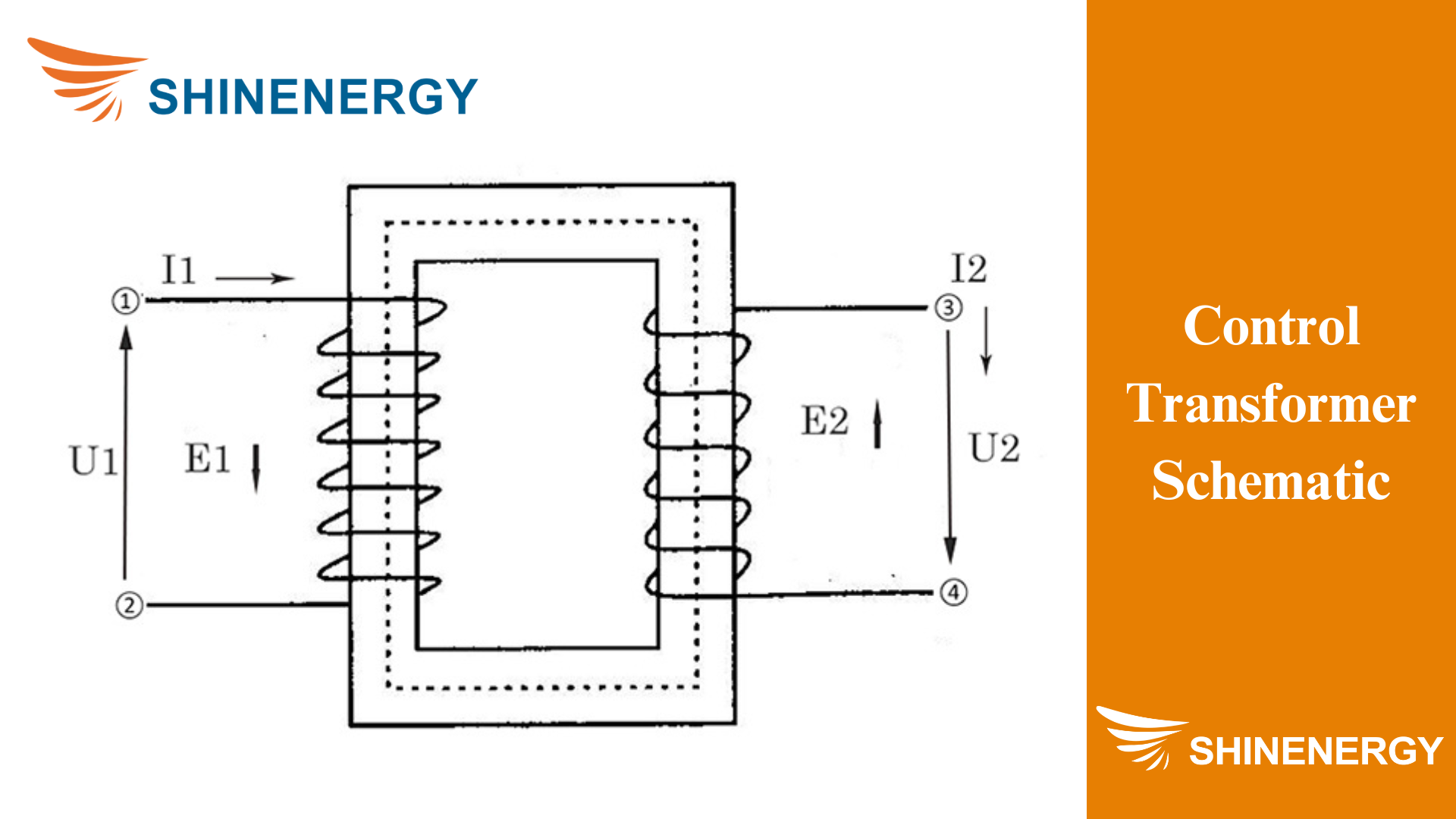
Figure 2-1 Control transformer schematic
control voltage transformers
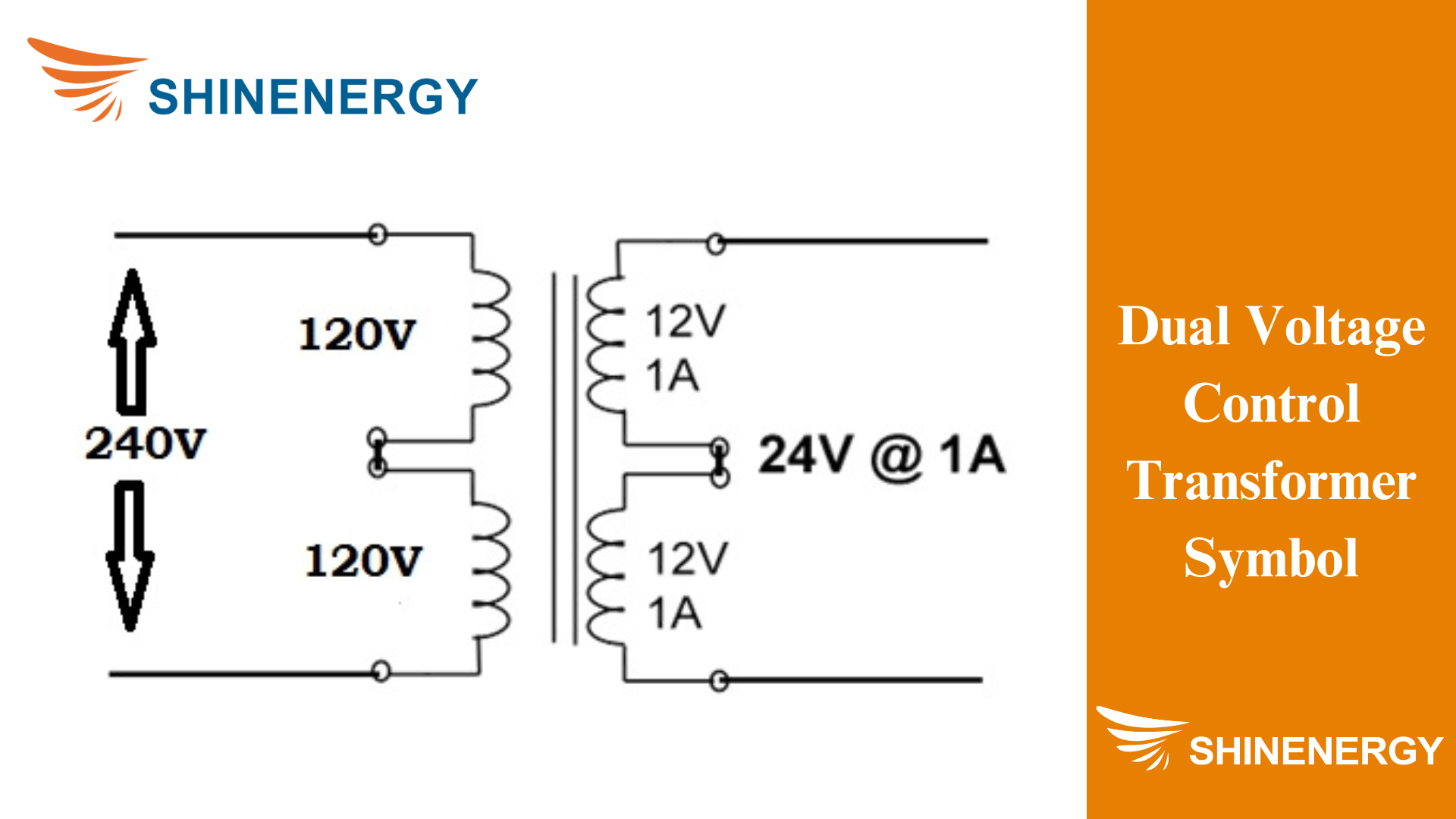
Figure 2-2 Dual voltage control transformer symbol
Control voltage transformers are transformers used to convert a high voltage to a lower control voltage (such as 208 to 120 control transformer、220v to 110v control transformer、 24-volt control transformer、240v to 24v control transformer、277v to 120v control transformer) in order to provide a stable, safe power supply to control circuits and equipment. These transformers are very common in industrial and commercial applications. Especially where precise control and protection of sensitive electrical components are required. Such as low-voltage control transformers and medium-voltage control transformers
enclosed control transformers
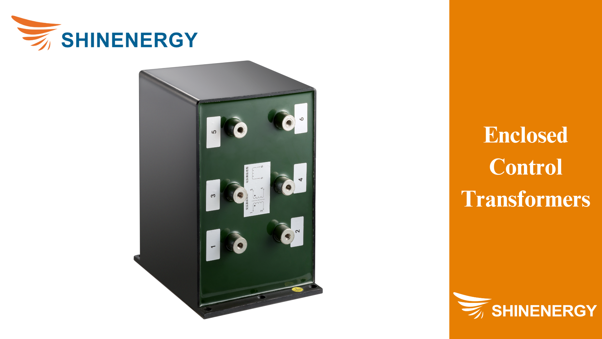
Figure 2-3 enclosed control transformers
An enclosed control transformer is a transformer enclosed in protective housing, specifically designed to convert the high voltage of the main power supply to the low voltage required by the control circuit. This enclosed design not only protects the transformer itself but also improves the safety of installation and operation. They are widely used in various industrial and commercial environments, especially in places with harsh conditions.
Low-voltage transformers with remote control allow users to conveniently manage and adjust the power supply from a distance, making it ideal for modern home automation systems and industrial applications.
control power transformers
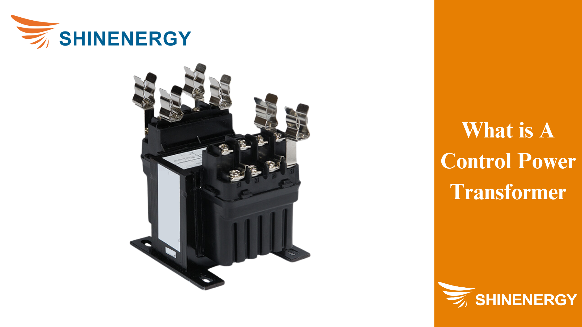
Figure 2-4 What is a control power transformer
A control power transformer is a transformer designed to provide a stable low-voltage power supply, especially suitable for various electrical control systems. They are usually used to convert high voltage (such as medium voltage control power transformer) to a low voltage suitable for use in control circuits (such as 480v to 120v control power transformers, 480v to 120v control transformer wiring diagram, 480v to 24v control transformer) to ensure the safety and normal operation of these circuits and equipment.
industrial control transformer
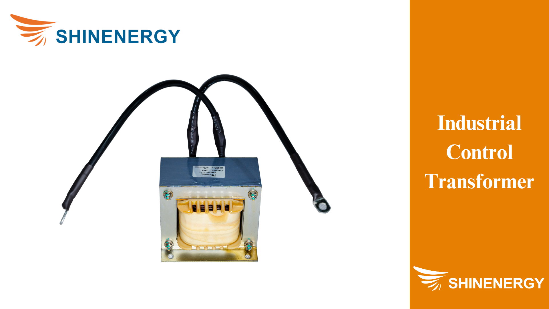
Figure 2-5 industrial control transformer
Industrial control transformers are transformers used in industrial environments and are specifically designed to provide stable low-voltage power to control circuits. These transformers typically convert high voltages (such as 120V or 240V) in industrial power systems to lower control voltages (such as 24V or 48V) to supply control devices, relays, contactors, and other industrial automation equipment. The industrial control transformer market is vast, encompassing various applications and specialized transformers like Machine Tool Control Transformers and motor control transformers. Understanding an industrial control transformer wiring diagram is crucial for proper installation and maintenance, ensuring that these transformers efficiently power control circuits in demanding industrial settings.
3-phase Control transformers
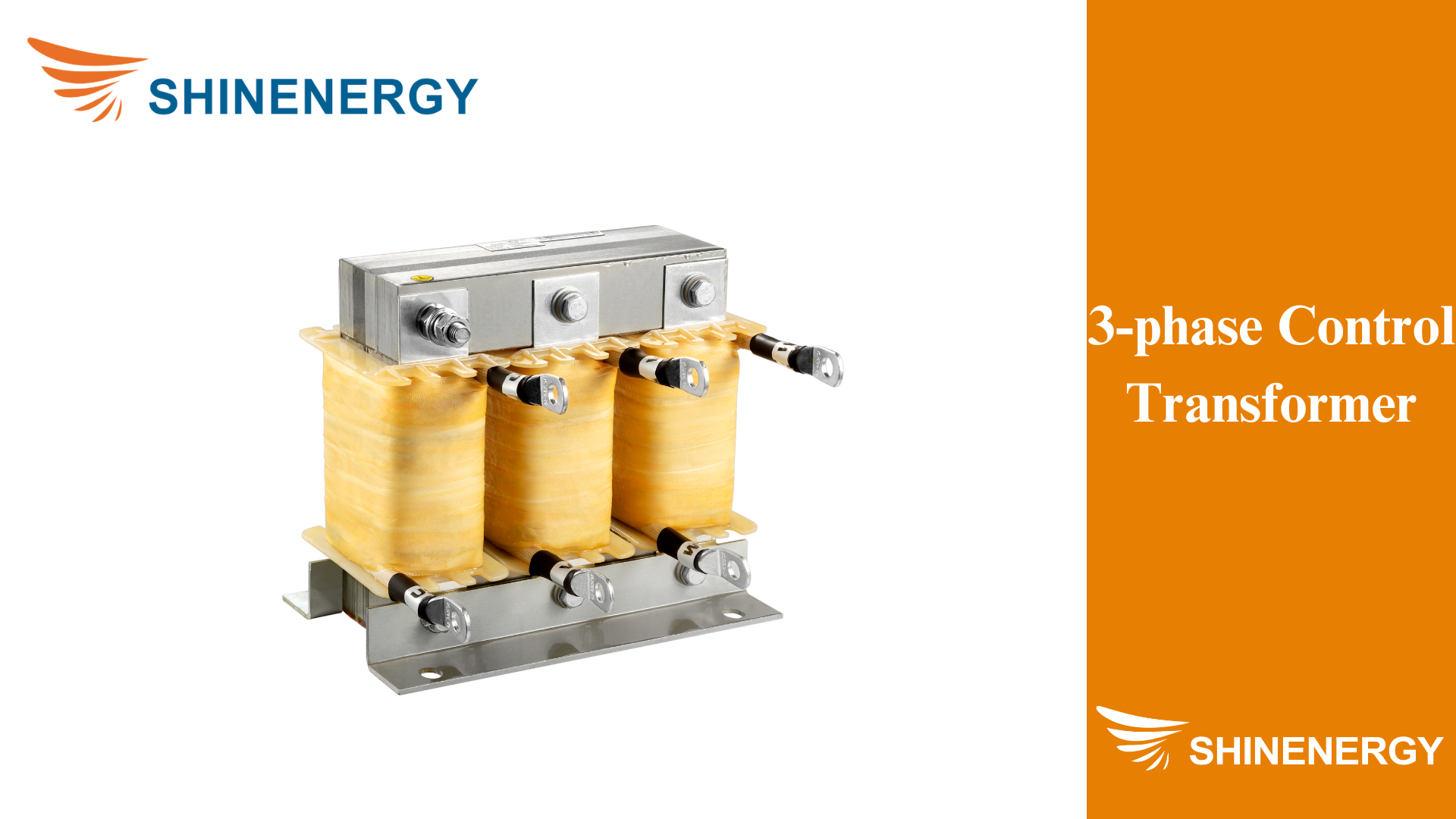
Figure 2-6 3-phase control transformer
A three-phase control transformer is a transformer used to convert three-phase power (usually a higher voltage such as 480V, or 600V) into a lower control voltage (such as 24V, 48V, or 120V) in order to provide a stable power supply for various control circuits and equipment. Unlike single-phase control transformers, three-phase control transformers are able to handle higher power requirements and are suitable for more complex and large-scale industrial applications.
Single-phase Control transformers
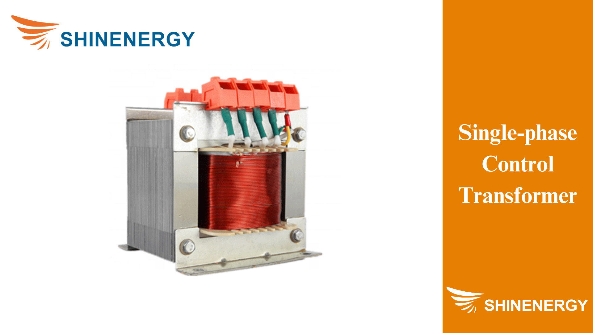
Figure 2-7 Single-phase control transformer
A single-phase control transformer is a transformer used to convert a single-phase power supply (such as 120V or 240V) to a lower control voltage (such as 24V or 48V). They are very common in industrial and commercial applications, especially where a stable low-voltage power supply is required for control circuits. Single-phase control transformers are suitable for systems with smaller power requirements, and their applications are more extensive and flexible than three-phase control transformers.
furnace Control transformers
A furnace Control Transformer is a transformer used in heating systems, especially in gas furnaces and electric furnaces. The main function of these transformers is to convert high voltage to low voltage to provide stable power to the furnace’s control circuits and related components.
isolation control transformer
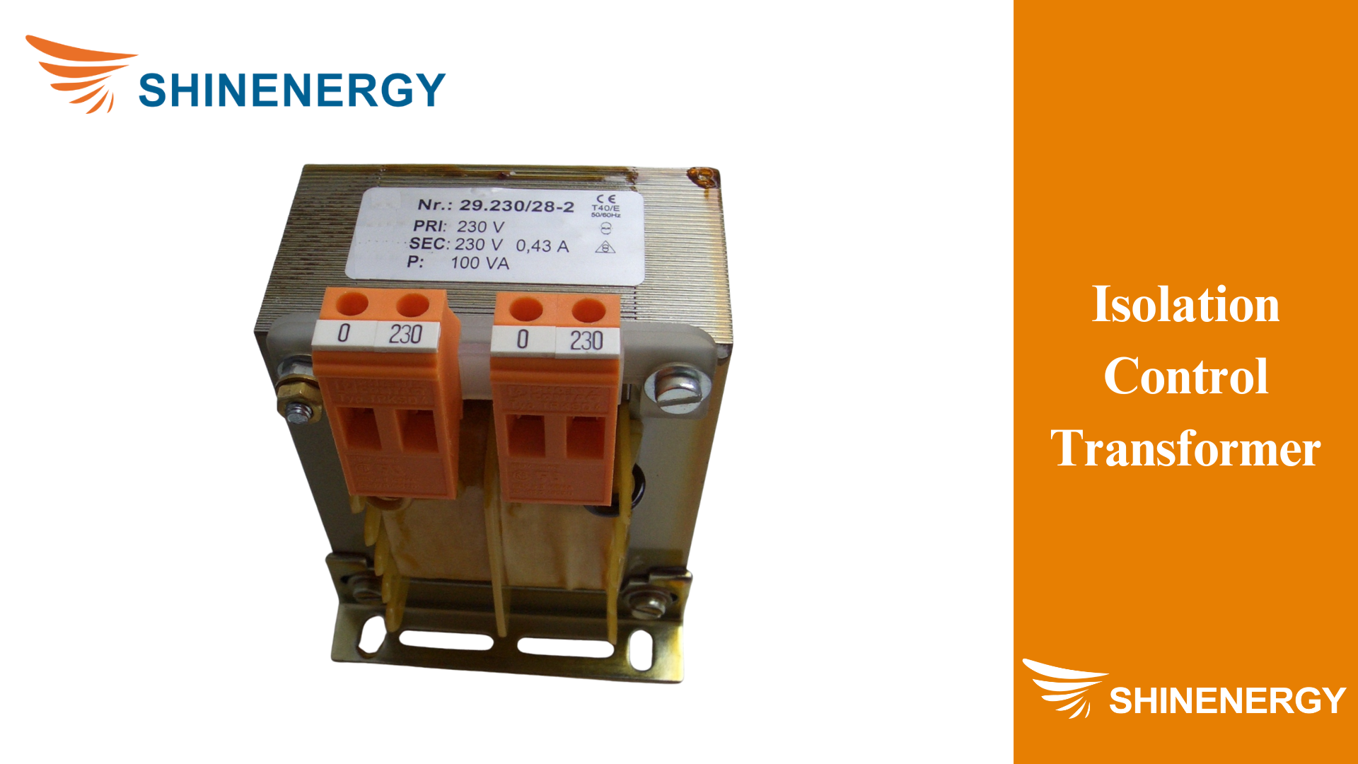
Figure 2-8 Isolation control transformer
It is a transformer specially designed for electrical control systems. Its main function is to provide a stable low-voltage power supply through electrical isolation while protecting the control circuits and equipment from power supply side faults and electrical noise.
Key Features of Control transformers
Figure 3-1 Key Features of Control Transformer
- Stable Voltage Output: most control transformers ensure consistent low-voltage power for control circuits, preventing voltage fluctuations.
- Mechanism of Providing Stable Voltage: Uses electromagnetic induction to convert high voltage to stable, low voltage.
- Electrical Isolation: Separates primary and secondary windings to protect control circuits from power surges and spikes.
- Safety and Protection Aspects: Enhances system safety by isolating control circuits from high-voltage sources, reducing fault risks.
- Noise Filtering: Filters out electrical noise and interference, ensuring smooth and accurate operation of control circuits.
- Reducing Electrical Noise and Interference: Minimizes disruptions in control systems by filtering out unwanted electrical noise.
- Durability: Built with high-quality materials and robust design to withstand harsh industrial environments.
- Design Features and Material Selection: Uses premium materials and sturdy construction for long-lasting and reliable performance.
Control transformer function:
Benefits of Using Control Transformers
Figure 4-1 Control transformer function
- Enhanced System Stability: Stable voltage ensures the smooth operation of control circuits, preventing system malfunctions.
- Importance of Stable Voltage for System Operation: Consistent voltage supply is crucial for the reliable performance of industrial and automation systems.
- Increased Safety: Electrical isolation protects both equipment and personnel from potential electrical hazards and faults.
- How Electrical Isolation Protects Equipment and Personnel: Separating high-voltage and low-voltage circuits, minimizes the risk of electrical shocks and damage.
- Prolonged Equipment Lifespan: Reduces electrical interference, thereby preventing premature wear and extending the life of control components.
- Reducing Damage Caused by Electrical Interference: Filters out harmful electrical noise, protecting sensitive control equipment from damage.
- Improved Efficiency: High-efficiency transformers save energy, reduce operational costs, and enhance overall system performance.
- Energy-Saving Effects of High-Efficiency Transformers: Efficient energy conversion minimizes power loss, leading to lower energy consumption and cost savings.
Applications of control transformers
Figure 5-1 1.5 kva control transformer
- Industrial Control Systems: Power automation equipment and control panels, ensuring reliable operation in industrial environments. Such as 1 kva control transformer、1.5 kva control transformer、1000va control transformer、100va control transformer、150 va control transformer、1kva control transformer.
- Automation Equipment and Control Panels: Provide stable voltage to control panels and automation machinery, ensuring smooth and efficient operation.
- Electrical Instruments: Deliver precise voltage to ensure accurate readings and measurements in various electrical devices.
- Providing Precise Voltage for Accurate Readings: Ensure that electrical instruments receive the correct voltage for precise data collection and monitoring.
- Machine Tool Control: Supply stable voltage to machine tools, ensuring precise and accurate processing.
- Ensuring Processing Precision with Stable Voltage: Maintain consistent voltage levels to ensure high precision and accuracy in machining operations.
- Lighting Control: Manage power for lighting systems, ensuring consistent and reliable illumination.
- Power Management for Lighting Systems: Provide stable power to lighting systems, preventing flickering and ensuring energy efficiency.
- Other Applications: Include various additional real-world use cases where stable low-voltage power is essential.
- Additional Real-World Use Cases: Cover a wide range of applications, from HVAC systems to security systems, requiring reliable power supply.
Custom Control Transformers:
Choosing the Right Control Transformer
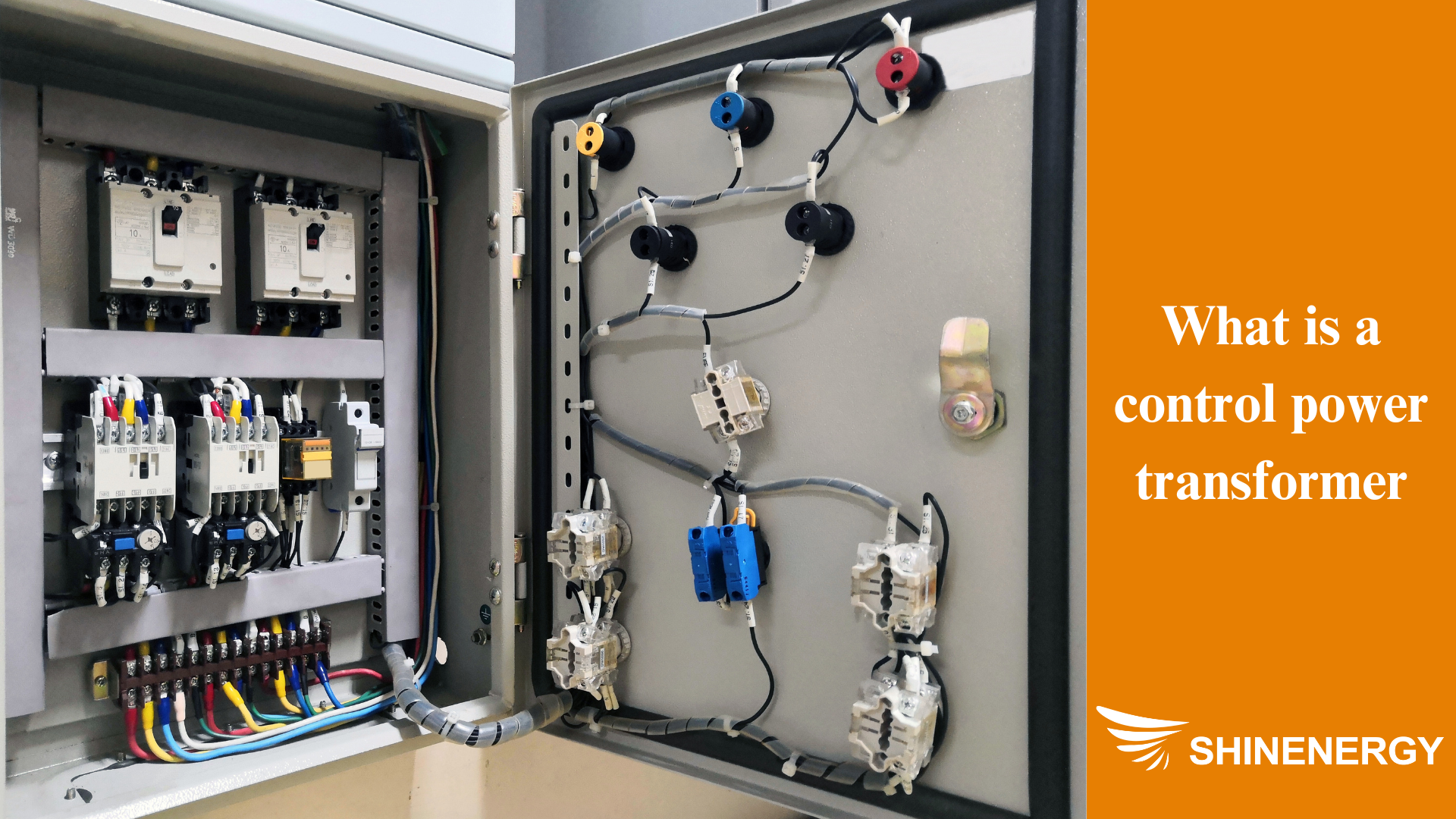
Figure 6-1 custom control transformers
- Determine Voltage Requirements
- Considerations for input and output voltage
- Assess Power Capacity
- Ensuring sufficient power supply
- Understand Frequency Requirements
- Selecting the appropriate operating frequency
- Consider Environmental Factors
- Temperature, humidity, and installation conditions
- Compliance with Regulations and Standards
- Ensuring safety and electrical standards compliance
FAQ
How do you choose the right control transformer?
Select a control transformer by determining the required input and output voltage, assessing the total power (VA) required by the control circuit, and considering the environmental conditions where the transformer will be installed.
How to size a control transformer?
Calculate the total VA (Volt-Ampere) requirement by summing up the VA ratings of all devices in the control circuit, then choose a transformer with a VA rating that meets or exceeds this total.
How to test a control transformer?
Test control transformers by measuring the input and output voltage with a multimeter to ensure it matches the specified ratings and check for continuity and insulation resistance.
How to wire a control transformer?
Wire control transformers by connecting the primary winding to the high-voltage input power source and the secondary winding to the control circuit, following the wiring diagram provided by the manufacturer. Ensure all connections are secure and follow electrical codes.
Why Does a Control Transformer Fuse?
- Overload: The total power demand of the control circuit exceeds the transformer’s rated capacity.
- Short Circuit: There is a short circuit in the transformer or the control circuit.
- Input Voltage Too High: The input voltage supplied to the transformer exceeds its design rating.
- Environmental Factors: The transformer overheats due to high ambient temperature or poor ventilation.
- Aging and Wear: The transformer components have aged or worn out from prolonged use.
- Manufacturing Defects: The transformer has manufacturing defects or quality issues.
- Power Fluctuations: The power supply is unstable, with frequent voltage spikes or control transformer blowing fuses.
How to Wire a Control Transformer?
- Turn off the Power: Ensure the power is turned off before starting any electrical wiring to prevent electric shock.
- Identify the Terminals: Locate the primary (input) and secondary (output) terminals of the transformer, usually marked as “Primary” or “P” and “Secondary” or “S.”
- Connect the Primary Terminals: Connect the high-voltage power supply wires to the primary terminals of the transformer, ensuring secure connections using appropriate methods (e.g., screws or terminal blocks).
- Connect the Secondary Terminals: Connect the secondary terminals to the control circuit, ensuring the wiring matches the transformer’s output voltage requirements.
- Grounding: Ensure the transformer’s casing or grounding terminal is connected to an appropriate ground wire to enhance safety and prevent electric shock.
- Control Transformer Wiring: Proper control transformer wiring is crucial to ensure that the transformer functions correctly and safely within the control circuit.
- Wiring a Control Transformer: When wiring a control transformer, always follow the manufacturer’s instructions and verify all connections to prevent electrical hazards.
What is a control transformer fusing? How do you calculate control transformer fuse sizing?
| Transformer Power (VA) | Input Voltage (V) | Primary Current (A) | Primary Fuse (A) | Output Voltage (V) | Secondary Current (A) | Secondary Fuse (A) |
| 50 | 120 | 0.42 | 0.5 | 24 | 2.08 | 2.5 |
| 100 | 120 | 0.83 | 1 | 24 | 4.17 | 5 |
| 150 | 120 | 1.25 | 1.5 | 24 | 6.25 | 7 |
| 200 | 120 | 1.67 | 2 | 24 | 8.33 | 10 |
| 75 | 240 | 0.31 | 0.5 | 24 | 3.13 | 4 |
| 150 | 240 | 0.63 | 1 | 24 | 6.25 | 7 |
| 100 | 240 | 0.42 | 0.5 | 48 | 2.08 | 2.5 |
| 200 | 240 | 0.83 | 1 | 48 | 4.17 | 5 |
| 300 | 240 | 1.25 | 1.5 | 48 | 6.25 | 7 |
control transformer fuse size chart/ control transformer fuse sizing chart/control transformer fuse chart
How do we calculate the VA rating of the control transformers?
Determine the Total Load:
Identify all devices powered by the control transformers, including relays, contactors, solenoids, indicator lights, etc.
Find the Power Requirements of Each Device:
Check the nameplate or specification sheet for each device to find its power consumption, usually listed in VA, watts, or amperes.
Convert Watts to VA (if necessary):
If the power consumption is given in watts, convert it to VA by dividing it by the power factor (if known). For simplicity, assume a power factor of 1.
Control Power Transformer Sizing:
Proper control power transformer sizing is essential to ensure that the transformers can handle the load requirements of the control circuit.
Control Transformer Rating:
When selecting a transformer, it is important to check the control transformer rating to ensure it meets the voltage and current needs of your application.
Control Transformer Protection:
Implementing adequate control transformer protection, such as using appropriate fuses, helps prevent damage due to overloads and short circuits.
What is the difference between a voltage transformer and a control transformer?
A voltage transformer is primarily used for stepping up or stepping down voltage levels in power distribution systems, focusing on transferring power efficiently. In contrast, a control transformer is designed to provide reduced and stable voltage specifically for control circuits, where the load often consists of relays, solenoids, and contactors that require precise voltage regulation and the ability to handle inrush currents.
How to choose a control transformer?
When choosing a control transformer, consider factors such as the required input and output voltage, the amount of inrush current the system will generate, the transformer’s capacity (VA rating), the operating environment, and protection features like fuse sizing and insulation class. Ensuring the transformer matches your system’s specific control circuit requirements is crucial for safe and efficient operation.
How does transformer electricity efficiency impact overall energy distribution in power systems?
Transformer electricity efficiency significantly impacts overall energy distribution in power systems. Efficient transformers reduce energy losses during voltage conversion, ensuring that more electricity reaches the end-users with minimal waste. Key factors affecting transformer efficiency include core materials, winding resistance, and the cooling method used. High-efficiency transformers lower operating costs and reduce the environmental impact by decreasing the energy wasted as heat. Therefore, choosing the right transformer for electricity distribution can optimize performance and contribute to a more sustainable power system.


Pingback: โบลเวอร์ kruger
Pingback: ถังน้ำตราบ้าน
Pingback: dental clinic krabi
Pingback: บุหรี่นอกราคาถูก
Pingback: essentials fear of god