

Shinenergy transformer wiring diagram helps electricians and engineers understand how to safely connect and install transformers in various systems. These diagrams vary by voltage, phase configuration, and intended function. This guide provides real-world wiring examples and clarifies common terms like Shinenergy transformer wiring diagram, Shinenergy transformer schematic, and wiring a transformer. Whether you are working on residential, commercial, or industrial projects, understanding how to read and apply these diagrams is essential. Transformer wiring diagrams help electricians and engineers understand how to safely connect transformers. These diagrams vary by voltage, phase configuration, and intended function. This guide provides real-world wiring examples and clarifies common terms like transformer wiring diagrams, transformer schematic, and wiring a transformer.

Wiring Diagrams by Voltage
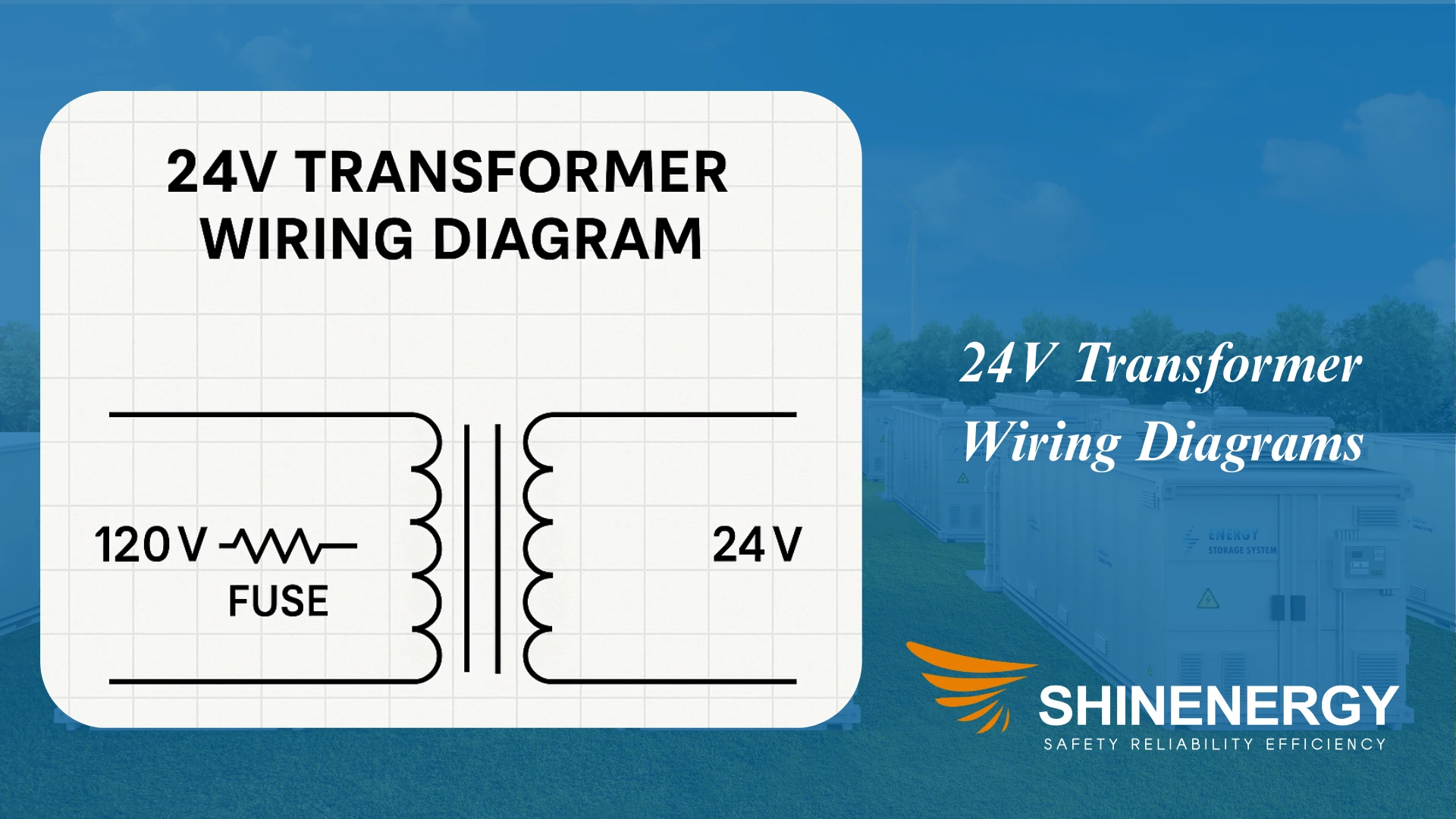
24V Transformer Wiring
doorbell transformer wiring diagram
24V transformers are common in control circuits and HVAC systems. A typical 24V wiring diagram for doorbell transformer shows a primary side connected to 120V or 240V, and a secondary output of 24 volt hvac transformer wiring diagrams.
120V to 24V Step-Down Transformer
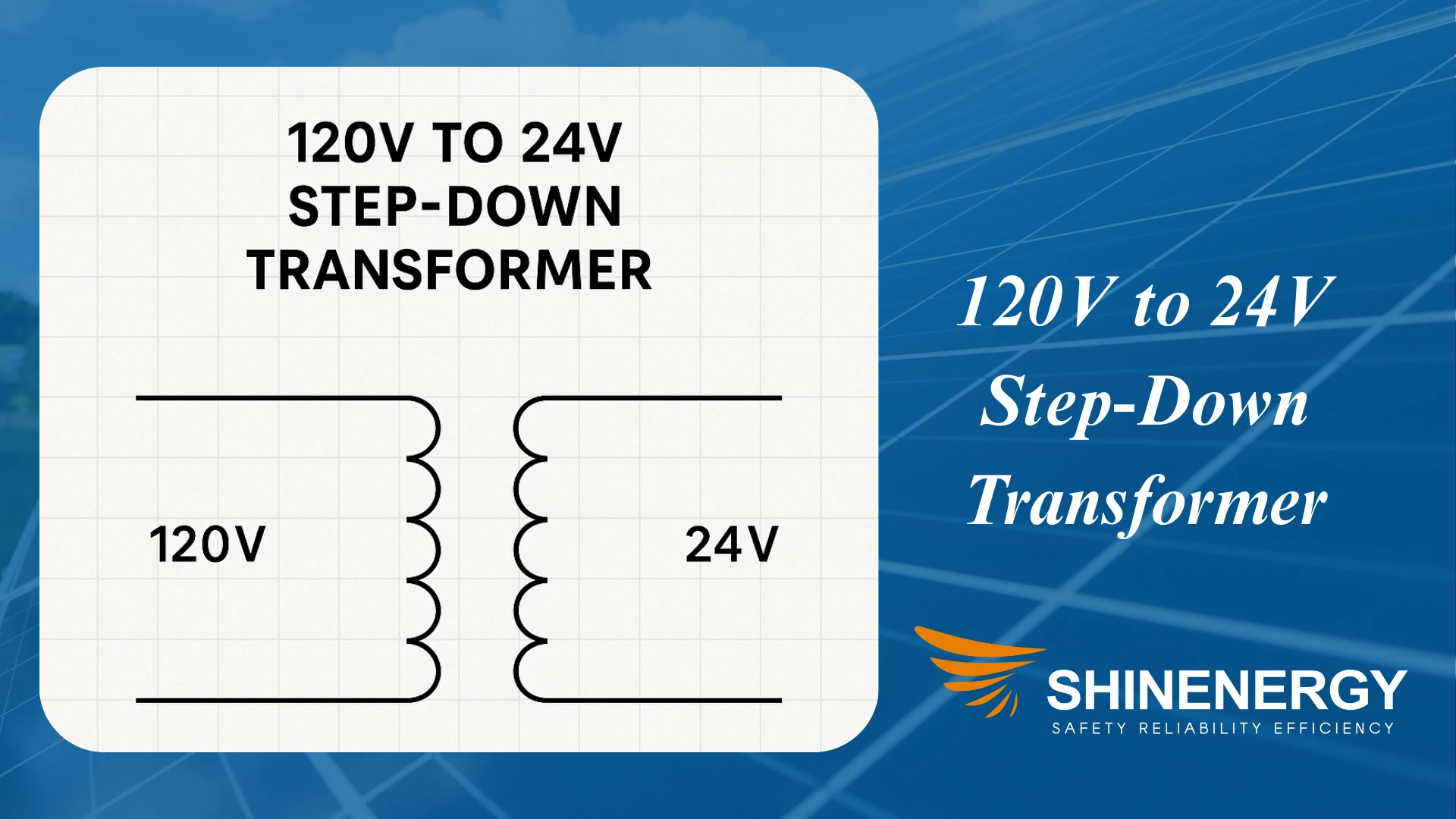
Wiring diagram for transformer. This setup is widely used in doorbells and thermostats. A 120 to 24 volt transformer wiring diagram often includes a fuse or circuit breaker between the line voltage and primary coil.
240V to 120V Transformer Wiring

This configuration is common in light industrial and residential applications. A 240V primary to 120V secondary step-down wiring diagram includes L1 and L2 inputs and a grounded center-tap secondary.
277V to 120V Transformer Wiring
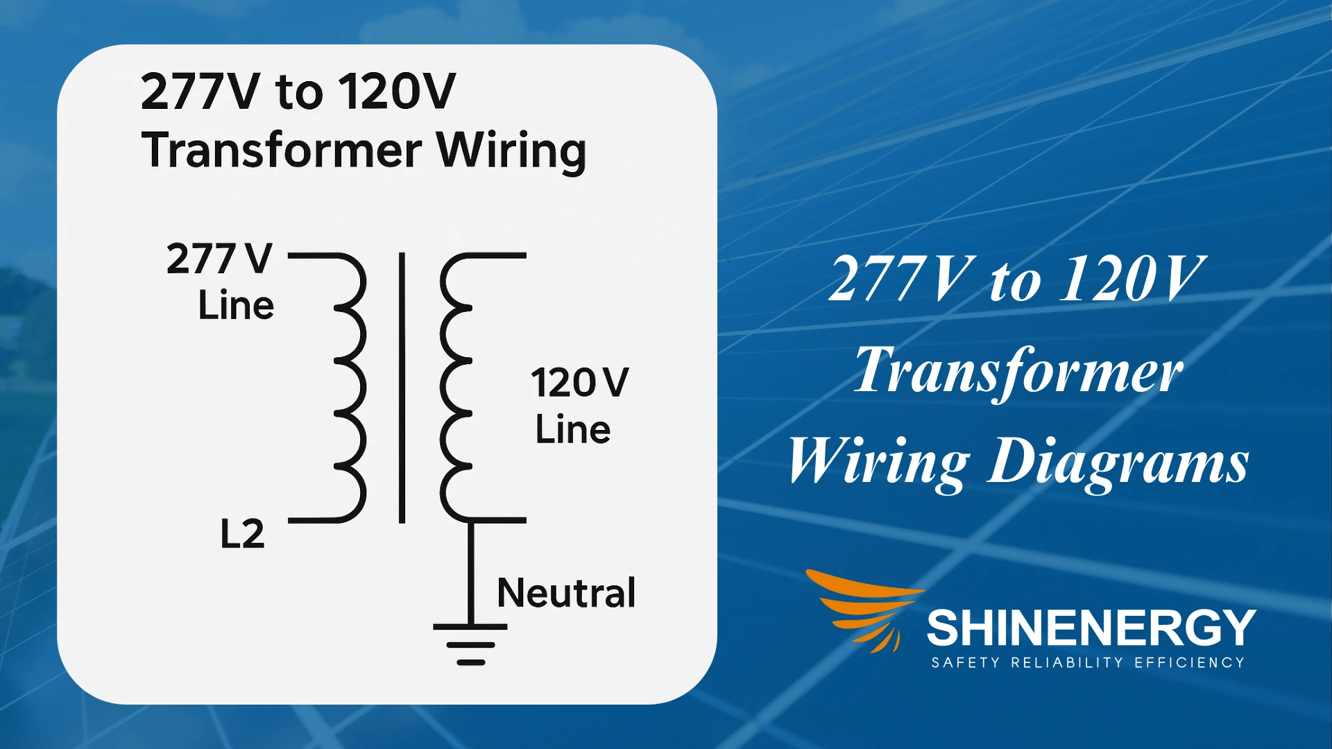
Wiring diagram of transformer. Used in commercial lighting systems, this setup requires careful attention to grounding and neutral paths. Diagrams for this setup typically show hot-neutral connection from 277V circuits.
480 to 208 transformer wiring diagrams or 480V to 120V transformer wiring
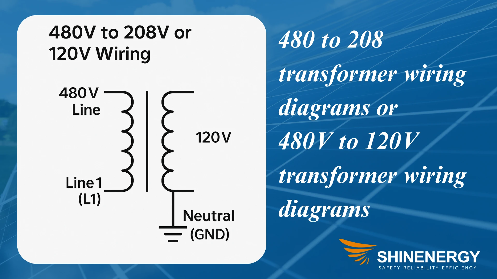
Wiring a transformer diagram,industrial environments use 3-phase 480V inputs to step down to 208V or 120V. A 480 to 120/240 transformer wiring diagrams helps identify correct winding tap connections.
480 to 120/240 transformer wiring
480 to 120 transformer wiring diagram
3 phase 480 to 240 transformer wiring diagram
Buck boost transformer 208 to 240 wiring
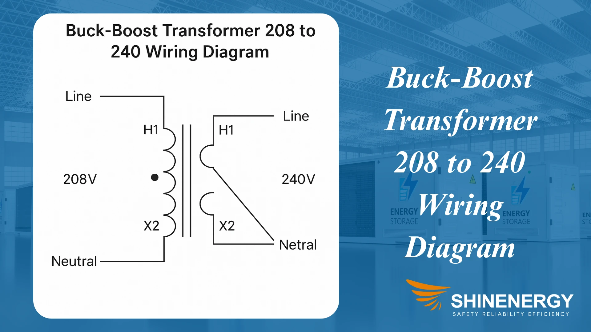
buck transformer wiring diagram/boost transformer wiring diagram
600V Transformer Wiring
In heavy industrial setups, transformers may receive 600V input and step down to lower voltages. A 600v transformer wiring diagrams should clearly mark L1, L2, L3 terminals, grounding lugs, and appropriate fuse protection.
Wiring Diagrams by Phase
2-Phase Transformer Wiring
Although less common in modern systems, 2-phase wiring diagram transformers can be found in older installations or legacy infrastructure. A 2 phase transformer wiring diagrams generally includes two primary windings and two secondary windings arranged 90 degrees out of phase. Clear labeling of the line leads and phasing is essential to prevent electrical mismatch.
Single Phase Transformer Wiring
single phase 480 to 120/240 transformer wiring diagrams are used in residential and light commercial applications. Diagrams show line (L), neutral (N), and ground (GND) terminals clearly.
Three phase transformer wiring
A 3 phase 480 to 240 transformer wiring diagrams usually features delta or wye (star) connections. Proper wiring ensures balanced load across all three phases.
Wiring Diagrams by Function
Step-Down Transformer Wiring
These 120v to 24v transformer wiring diagrams show how to reduce higher voltages to lower ones safely. 120v 24v transformer wiring diagrams often include fuses or circuit breakers.
Buck-Boost Transformer Wiring
Buck-boost transformers slightly adjust voltage levels. A buck boost transformer 208 to 240 wiring diagram, or 208v to 240v buck boost transformer wiring diagrams shows how to wire for small voltage increases.
Isolation Transformer Wiring
These diagrams illustrate galvanic separation between primary and secondary. Isolation transformers reduce noise and protect equipment.
Transformer Wiring Symbols & Schematics
Reading a Shinenergy transformer schematic or circuit diagram requires familiarity with common symbols such as coils, taps, fuses, grounds, and phase markings. A Shinenergy transformer circuit diagram offers a visual map of electrical flow and connection points, often including safety elements like circuit breakers and disconnects.
FAQ: Common low voltage transformer wiring diagrams Questions
Can you show a Shinenergy transformer schematic for audio or low-voltage use?
A: While we don’t produce audio-specific transformers, Shinenergy transformer schematic diagrams for power supply or control use often resemble audio-grade layouts. Always consult the manufacturer’s documentation.
How does a Shinenergy transformer relay wiring diagrams look in an HVAC circuit?
A: Shinenergy transformer relay wiring diagrams show the connection between a step-down transformer (usually 24V output) and the system control board. A fuse and a relay coil are typically shown on the low-voltage side.
Can I use a Shinenergy transformer wiring diagrams for a 5-wire setup?
A: Yes. A wiring diagrams for 5 wire transformers usually includes two hot wires, one neutral, one ground, and a low-voltage control wire. Shinenergy transformer wiring diagrams follow NEC color coding for clarity and compliance.
What is a Shinenergy electrical transformers wiring diagram used for?
A: Electrical transformers’ wiring diagrams by Shinenergy help installers safely connect multi-voltage systems. They include tap configuration, phase matching, and grounding practices.
How do I interpret a Shinenergy comtrol transformer wiring diagram?
A: Control transformers are used to power contactors and PLCs. A Shinenergy comtrol transformer wireing diagram shows primary voltage input and low-voltage outputs for circuit logic.
What is a Shinenergy ignitor transformer wiring diagram?
A: These diagrams apply to systems where a transformer supplies ignition voltage (such as gas burners). Shinenergy ignitor transformer wireing diagrams include high-voltage secondary coils and grounding isolation.
How do I wire a transformer diagram correctly?
A: Always follow manufacturer instructions and refer to standard transformer wiring diagrams to match voltage, phase, and grounding.
What is a transformer hook up?
A: Hooking up a transformer means connecting the primary and secondary sides safely, sometimes called transformer hook-up or wiring hook-up.
What does XFMR mean?
A: XFMR is shorthand for “transformed,” often used in wiring diagrams.
Pingback: HILO789
Pingback: vaksin umrah johor bahru
Pingback: LSM99
Pingback: บทความ LSM99
Pingback: rolling tobacco uk
Pingback: altogel
Pingback: เลือกบริษัทขนส่งจากจีน
Pingback: Peptide Gray Market In China
Pingback: altogel
Pingback: Pinnacle เว็บเดิมพันกีฬาออนไลน์อันดับ 1