

In modern power systems, transformers serve as core equipment for energy transmission and distribution. Their performance directly affects overall system efficiency and stability. Among the many components of a transformer windings, the winding is undoubtedly the key element responsible for voltage transformation and energy transfer.
This article provides an in-depth exploration of transformer windings, covering basic concepts, common types, manufacturing processes, and key design considerations for real-world applications. Through structured analysis and practical examples, it aims to offer a comprehensive knowledge framework to support professionals in transformer design and production.
P1-windings
Basic Concepts and Classification of Transformer Windings
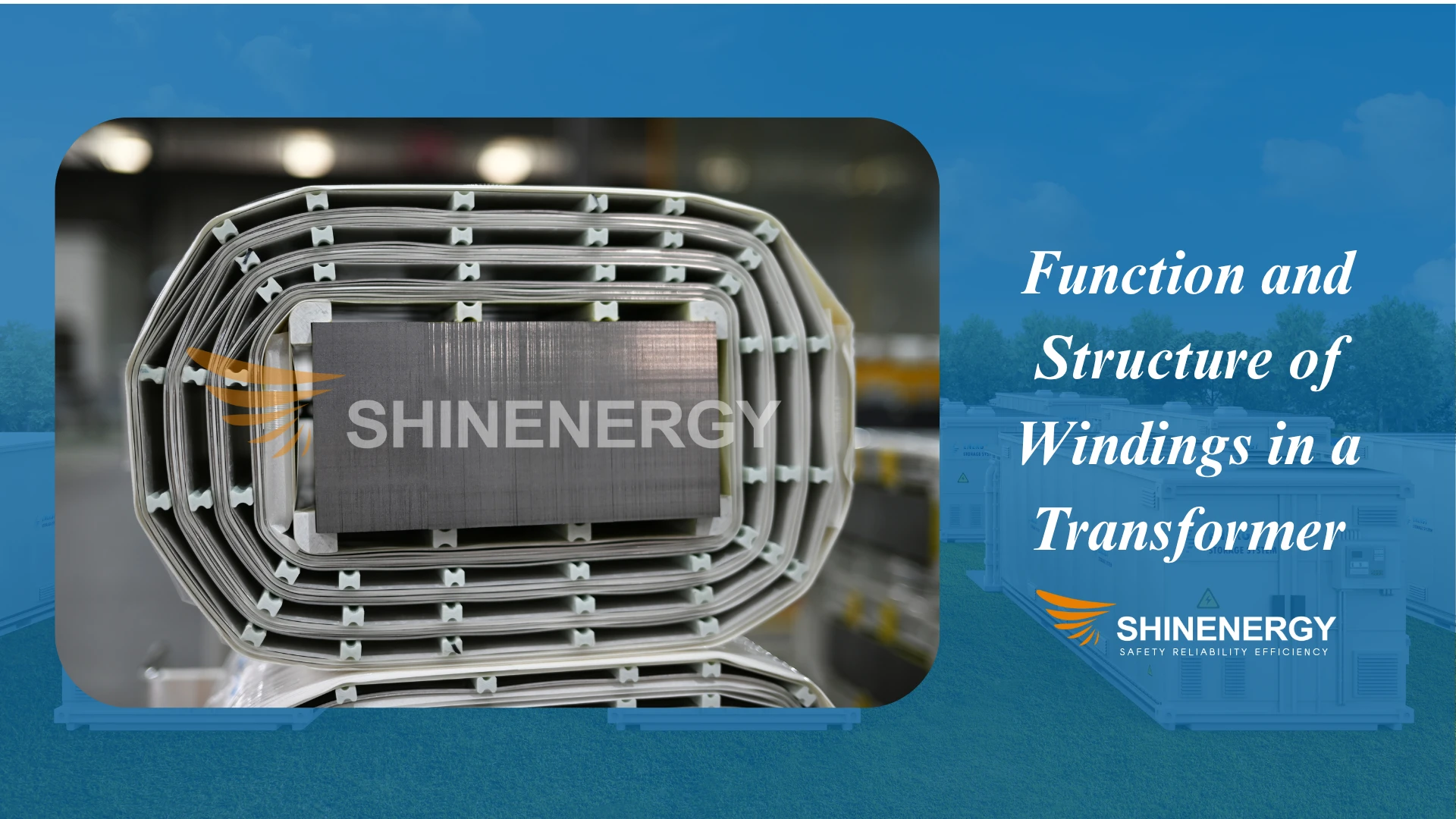
Function and Structure of Windings in a Transformer
P2-transformer winding
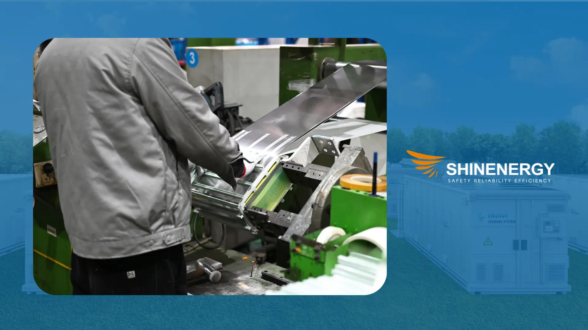
What are windings? Transformer windings determine how electrical energy is transferred and converted between voltage levels. They are made of insulated conductors—typically copper or aluminum—wound around the magnetic core. The layout forms two magnetically coupled circuits: the primary and the secondary winding.
The primary winding connects to the power grid and generates alternating magnetic flux. This flux passes through the core and induces electromotive force (EMF) in the secondary winding. There is no electrical connection between the two; energy transfer occurs purely through magnetic coupling.
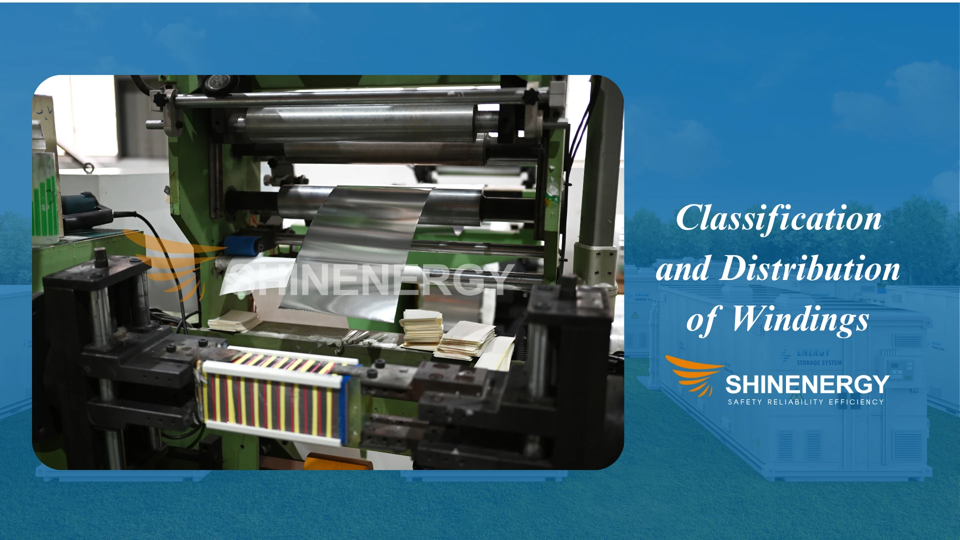
Classification and Distribution of Windings
P3-transformer windings
Based on function, transformer windings can be grouped into three types: main windings (primary and secondary), high/low-voltage windings, and auxiliary windings.
The main windings perform the core transformation task. The primary winding connects to the power source, while the secondary winding delivers power to the load. Their design must account for the required number of turns, voltage level, and power rating.
The high-voltage winding is typically wound closer to the magnetic core.
This layout minimizes the voltage difference between winding and ground, enhancing insulation safety.
In contrast, the low-voltage winding is usually positioned on the outer side, which facilitates cooling and external connections.
This is often referred to as the “HV-in, LV-out” configuration.
Auxiliary windings do not participate in the main energy transfer.
They are used for voltage sensing, control signals, or internal power supply.
For example, UPS transformers often include a feedback winding for voltage regulation or protection circuits.
Some custom transformers include additional winding branches, such as tertiary windings, tapped windings, or multi-ratio secondary windings.
These are commonly found in voltage regulators, DC-DC converters, and renewable energy systems.
A clear understanding of winding distribution is essential for designing a transformer that is efficient, safe, and stable under load.
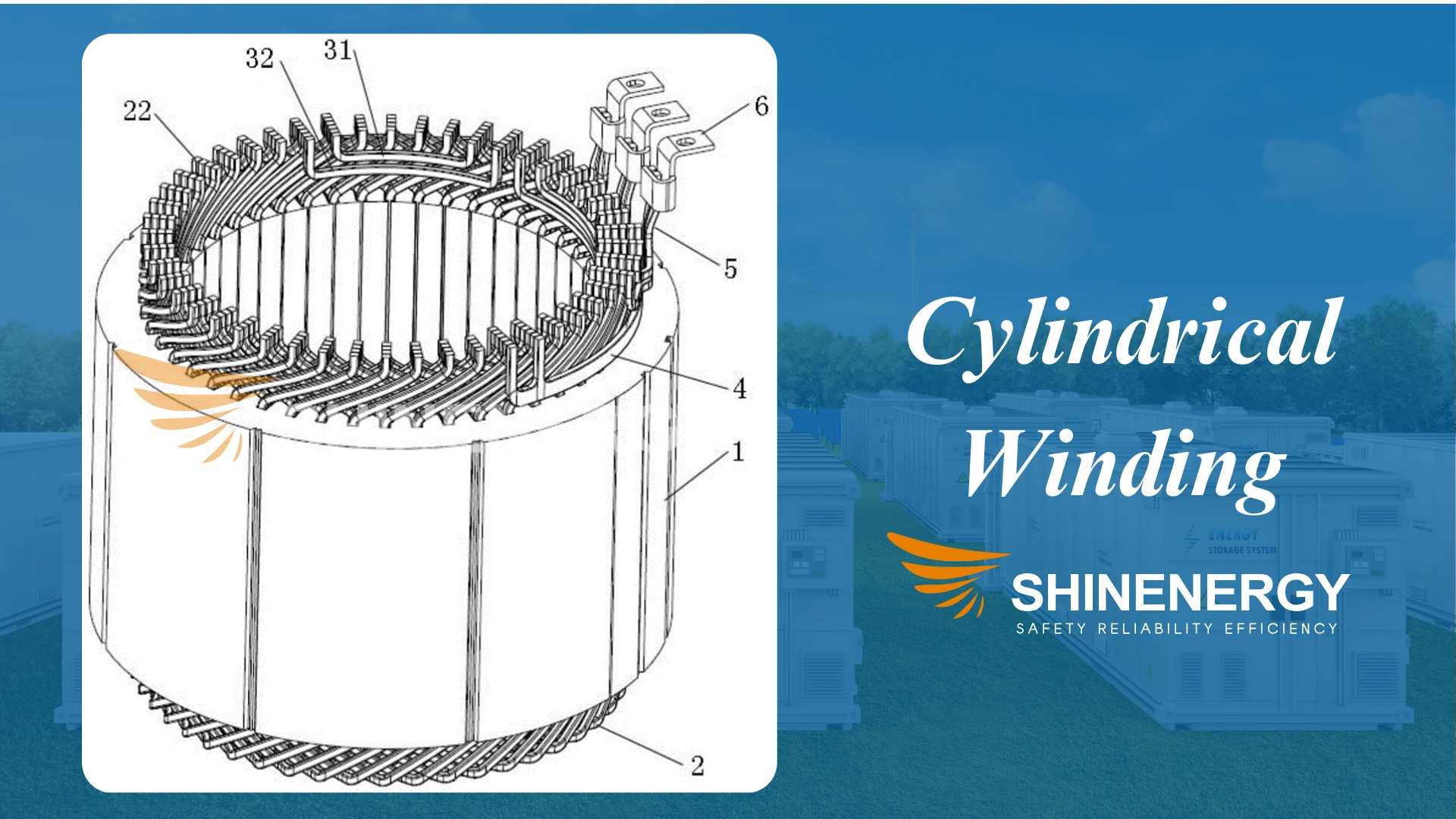
Cylindrical Winding
P4- Cylindrical Winding
Structure and Design
Cylindrical winding uses insulated conductors arranged around a cylindrical winding device.
The turns build up axially and form a compact, layered coil.
This method follows a concentric winding pattern.
Each layer surrounds the previous one in a symmetrical radial layout.
A concentric winding diagram clearly shows this structure.
Engineers adjust the radial build and axial length based on voltage and current needs.
They use either round wire or rectangular wire, depending on current density.
Each layer includes layer insulation to handle electrical stress.
Sometimes, they use paper-insulated wire for added dielectric strength.
Compared with lap winding, concentric winding offers easier layout and better thermal flow.
This design also suits automated manufacturing.
Modern factories use programmable cylindrical winding devices to ensure consistency.
Application and Technical Considerations
Cylindrical winding in transformers fits low-voltage, high-current applications.
It appears commonly in dry-type transformers and distribution transformers.
It also supports mass production due to its low cost and repeatable geometry.
This winding form appears in many concentric winding transformers and concentric winding motors.
It works well where tight winding tolerances and short cooling paths are important.
The structure allows efficient natural or forced-air cooling.
That makes it suitable for compact, enclosed enclosures.
In concentric winding induction motors, the design ensures low vibration and good symmetry.
This improves performance in demanding electromechanical systems.
Compared with other methods, concentric coils and transformers show lower internal capacitance.
However, they offer limited short-circuit strength
That’s why engineers rarely use this structure in high-voltage transformers.
Debates continue on lap winding and concentric winding.
Still, most manufacturers favor concentric types for standard low-voltage builds.
Its simplicity, manufacturability, and stable performance make it a reliable choice.
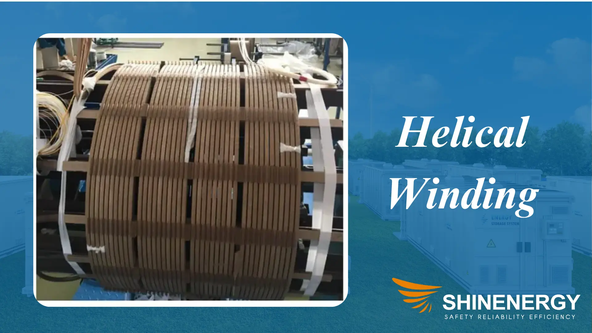
Helical Winding
P5-Helical Winding
Structure and Working Principle
Helical winding is built by arranging conductors in a continuous spiral along the axial length of the coil.
Each turn forms a single layer, making the structure open and easy to cool.
This method is ideal when using wide strip or foil conductors that carry large current.
In a helical winding transformer, turns must be carefully spaced.
Engineers insert insulation between each turn to prevent voltage breakdown, especially in high-stress areas.
The design naturally reduces AC resistance because the current path remains short and direct.
During manufacturing, a helical winding machine handles turn spacing, tension, and angle.
The helical winding process requires strict mechanical precision to avoid issues like turn buckling or uneven tension.
Use Cases and Advantages
You’ll often find helical winding in transformers rated over 400 kVA.
It suits low-voltage, high-current applications where compact layout and strong thermal performance matter.
This includes dry-type transformers used in industrial plants, data centers, and transport systems.
Helical coils offer excellent cooling thanks to their exposed surface and natural airflow.
The structure also resists mechanical forces during short circuits better than simple layer windings.
However, this method demands high production accuracy.
Loose turns can lead to movement under thermal cycling, increasing the risk of internal failure.
To avoid this, many helical winding transformers undergo vacuum pressure impregnation (VPI) after winding.
This locks the entire structure in place with resin, improving both strength and insulation life.
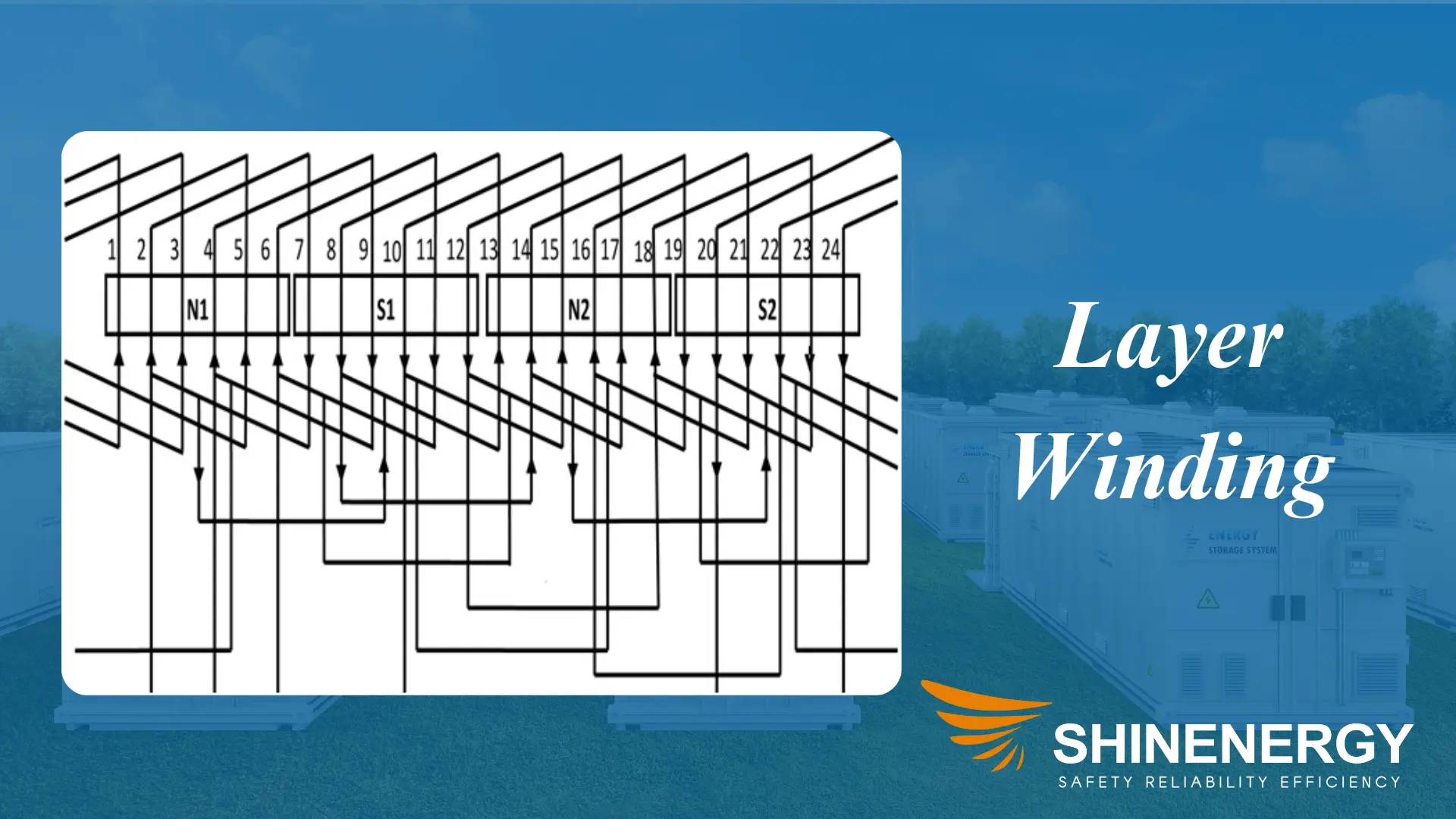
Layer Winding
P6-Layer Winding
Structure and Insulation Method
Layer winding arranges conductors neatly in stacked layers.
Each layer lies parallel along the coil length.
After one layer is completed, the operator or machine adds insulation—typically paper or fiberglass tape—before continuing the next layer.
This method keeps turn voltage low and layout highly organized.
The entire coil becomes dense and symmetrical, ideal for resin impregnation or oil immersion.
Engineers often use a layer winding machine for repeatable precision.
For small to medium power ratings, layer winding in transformers is a practical and cost-effective choice.
Variants: Single vs Double Layer Winding
There are two main types: single layer winding and double layer winding.
In single layer winding, one conductor wraps continuously across the layer before moving to the next.
It works well in simple coils where high slot fill is not required.
A single layer winding diagram shows one conductor path per slot.
In double layer winding, two coil sides share the same slot—one at the top, one at the bottom.
This improves magnetic balance and suits three-phase systems.
A double layer winding diagram or 3 phase double layer winding diagram shows this staggered layout.
You’ll also find detailed layouts like the 36 slot 4 pole double layer winding diagram, common in induction motor stators.
Understanding the difference between single layer and double layer winding helps match the right design to the application.
Single layer and double layer winding methods differ in complexity, magnetic symmetry, and conductor packing factor.
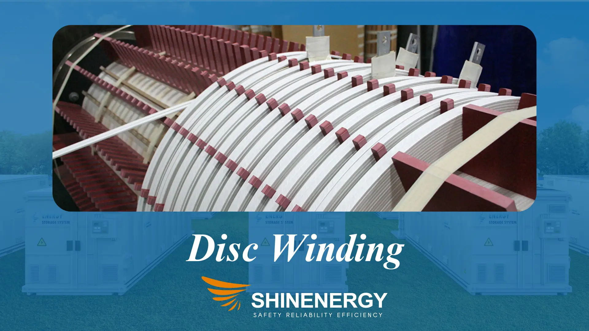
Disc Winding
P7-Disc Winding
Structure and Winding Method
Disc winding builds the coil by forming multiple flat discs from insulated conductor.
Each disc lays in a single plane, then all discs are stacked vertically to form a complete winding.
This method ensures that voltage stress distributes evenly along the axial direction.
A standard disc winding in transformer design uses several identical discs.
Engineers add insulation ducts between them to allow for oil circulation and cooling.
These ducts also reduce hot spots and extend insulation life.
The process requires precise winding tension control.
Inconsistent tension leads to uneven disc size, which can compromise performance and increase vibration risk.
There are two common styles:
Continuous disc winding, where the conductor flows across discs without splicing.
Interleaved disc winding, where conductors weave between discs to reduce surge voltage stress.
Each style suits a different voltage range or impulse withstand level.
Continuous disc winding in transformer designs often appear in long-duty high-load conditions.
Applications and Design Advantages
Disc winding is the go-to method for high-voltage, high-capacity units.
It is standard in power transformers rated 110 kV and above.
This includes grid interconnection transformers, large generator step-up units, and critical substation equipment.
The structure provides strong short-circuit strength and low axial electric stress.
Oil flows naturally through the winding due to built-in insulation channels between discs.
When mechanical forces rise during faults, the disc stack resists deformation better than conventional coils.
This makes disc winding transformers highly reliable under dynamic load conditions.
While manufacturing takes more time and precision, the long-term thermal and dielectric performance makes it worthwhile.
For any transformer above 63 MVA or 110 kV, disc winding remains a proven, trusted choice.
Crossover Wining
Crossover winding arranges conductors in a crisscross pattern to minimize leakage inductance and stray capacitance.
It’s used mainly in high-frequency transformers like those in switch-mode power supplies.
The design helps improve response speed and reduce electromagnetic noise.
However, it requires tight insulation control and high-precision winding.
Due to its complexity and niche application, crossover winding is typically limited to small, high-frequency coils in electronic circuits.
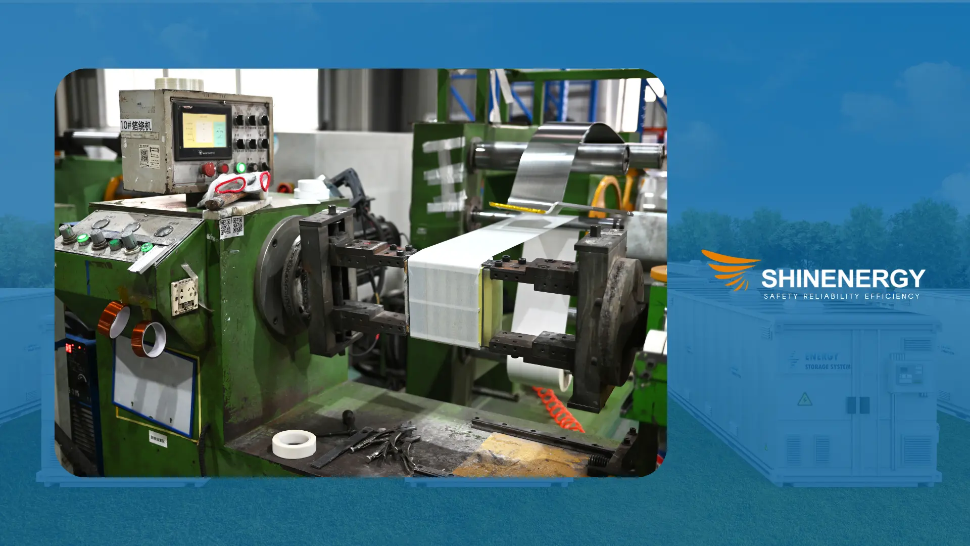
Foil Winding
P8-Foil Winding
Transformer Windings:Structure and Technical Features
Foil winding uses thin, wide strips of copper or aluminum foil as conductors.
Each foil layer stacks flat in a single turn, with insulation tape applied between layers.
This geometry ensures uniform current density and minimizes skin effect, even at higher currents.
The conductors lie in close, planar contact with adjacent layers.
This improves heat dissipation and reduces parasitic reactance.
Because of its flat profile, foil winding offers better axial cooling and tighter coil geometry.
Manufacturing requires a foil winding machine, which applies foil, insulation, and edge alignment in one pass.
Options include copper foil winding machines, aluminum foil winding equipment, and multi foil winding machines for stacked or split-phase designs.
The foil winding process also supports programmable tension control, precise width alignment, and easy resin impregnation.
Tolerances are tight—especially in transformer foil winding with thermal class F or higher.
Transformer Windings:Applications and Equipment Use
Foil winding in transformers is common in low-voltage, high-current systems.
Typical applications include arc furnace transformers, rectifier units, EV chargers, and power distribution reactors.
In dry-type systems, foil windings reduce noise and hotspots.
In oil-immersed units, the flat coil face promotes steady oil flow and efficient convection.
Production lines often integrate OEM LV foil winding machines or OEM HV foil winding machines, depending on voltage class.
An OEM transformer foil winding machine supports bulk manufacturing while maintaining consistent quality.
Some factories use hybrid systems with interchangeable heads for switching between Cu and Al.
That allows one foil winding machine for transformers to serve multiple SKUs and order types.
Because foil coils are compact, strong, and thermally stable, they are now the default in many modern foil winding transformers.
Multi-Layer Helical Winding
Multi-layer helical winding stacks several conductor layers within a single helical coil.
Each layer is separated by insulation, ensuring better axial voltage distribution.
This design combines the thermal advantages of helical winding with improved dielectric strength.
It’s commonly used in dry-type transformers rated at 35 kV and above, especially where voltage stress needs to spread evenly.
The structure allows for compact winding layouts while maintaining strong short-circuit and thermal performance.
Disc-Helical Winding
Disc-helical winding combines the features of disc and helical structures into a hybrid coil design.
It suits ultra-high voltage and high-current transformers, typically above 110 kV.
The structure offers excellent mechanical stability and strong short-circuit resistance.
Because of its complexity, it requires advanced manufacturing equipment and precise control.
Common applications include power grid transformers and railway traction systems where both voltage endurance and thermal performance are critical.
Sandwich Winding
P9-Sandwich Winding
Sandwich winding arranges primary and secondary coils in alternating layers—for example, “primary-secondary-primary” or “secondary-primary-secondary.”
This layout increases magnetic coupling and significantly reduces leakage inductance.
Sandwich winding in transformers is common in high-frequency, high-efficiency designs, such as switch-mode power supplies and IGBT driver transformers.
The structure is compact, with concentrated thermal paths, so effective cooling is essential.
Its tight coupling improves energy transfer and supports faster switching performance.
Engineers often choose it for precision power electronics where layout symmetry and low noise matter.
Vertical Winding
P10-Vertical Winding
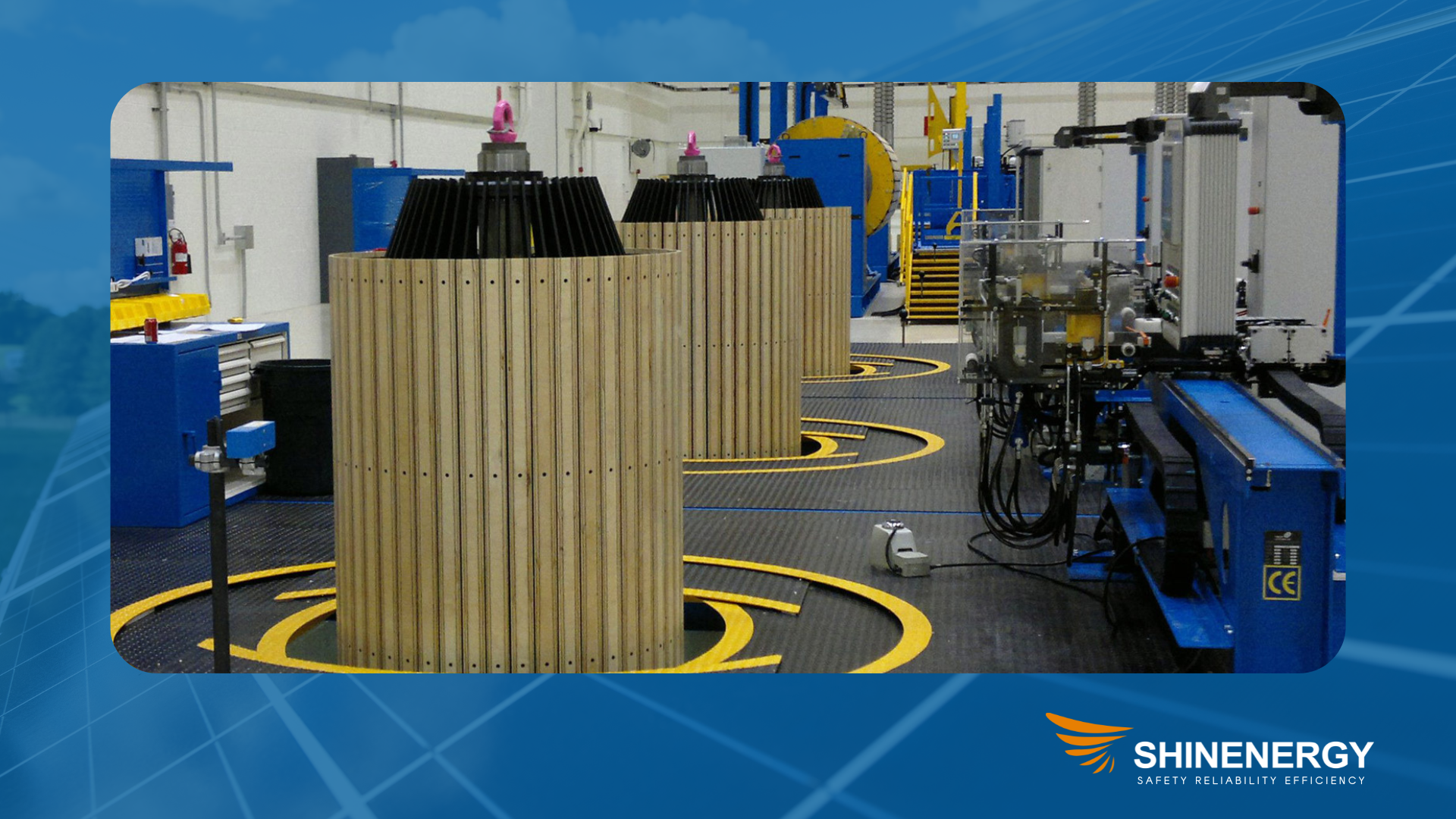
Vertical winding arranges conductors in an upright, pillar-like formation using automated winding systems.
The wire winds upward in vertical loops, producing compact and consistent coil geometry.
A vertical winding machine controls turn pitch and tension with high precision.
This method suits high-current coils requiring dimensional stability and repeatability—especially in dry-type reactors and transformers.
Winding speed is fast, and the output remains consistent across batches.
Shinenergy uses advanced vertical winding equipment to ensure tight tolerances.
When combined with VPI (Vacuum Pressure Impregnation), the coils gain excellent thermal and dielectric strength.
The process is ideal for applications like data centers, EV power modules, and high-frequency energy storage systems where thermal control and electrical reliability are critical.
How Transformer Windings Are Made
P11-coil and winding
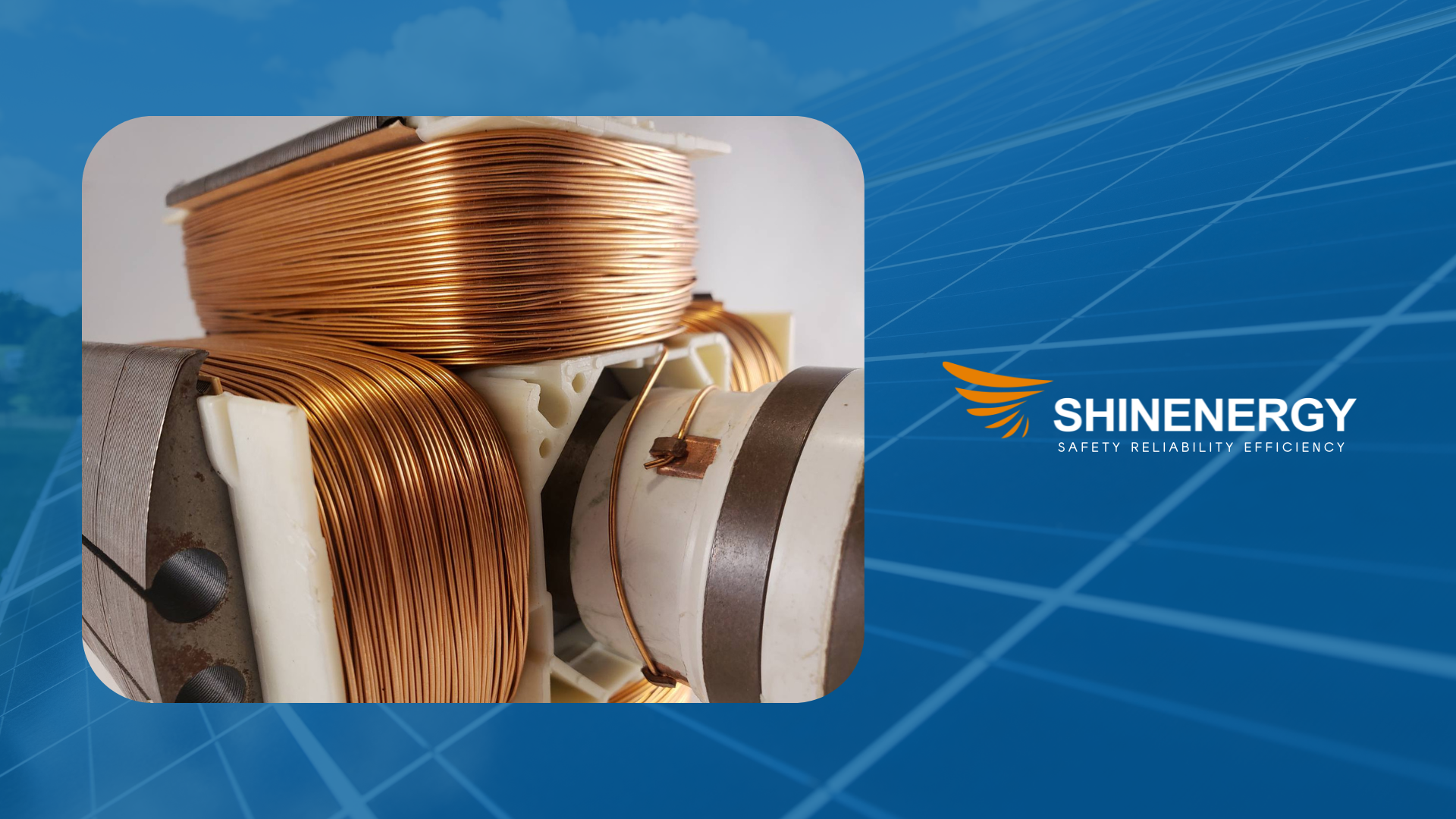
The performance of any transformer begins with precision in its coil and winding process.
From material selection to testing, every step impacts the final electrical, thermal, and mechanical quality.
Here’s how transformer windings are built in modern manufacturing lines.
Conductor Preparation
Every transformer coil starts with the right conductor.
Manufacturers choose between copper and aluminum, depending on cost, current rating, and design goals.
The wire is cleaned, tension-calibrated, and, if needed, edge-treated for insulation safety.
In some coil winding lines, foil may replace round wire for high-current applications.
Coil Winding
what are coils? The prepared conductor goes through an automated transformer winding machine.
This step defines turn count, layer build, and winding layout.
Different machines support vertical winding, disc winding, or foil winding, depending on the product type.
Precision matters: consistent tension and alignment reduce hotspots and noise in the finished transformer.
Layer Insulation and Separation
Between turns and layers, workers apply layer insulation using paper, film, or fiberglass.
Proper insulation spacing is critical to withstand voltage stress and avoid breakdown.
In secondary winding transformers, tighter winding often requires multi-layer dielectric barriers.
Modern winding equipment integrates insulation feed directly into the coil path.
Impregnation and Curing
Once wound, the transformer windings are vacuum-treated and resin-impregnated.
This is often done using VPI (Vacuum Pressure Impregnation) to fill microscopic gaps.
Curing under heat hardens the structure and locks conductors in place.
The result: better thermal endurance, lower vibration risk, and improved lifespan.
Assembly and Final Testing
The finished coils are then assembled with the transformer core.
Technicians conduct a full test sequence, including:
- Winding resistance
- Turns ratio
- Insulation resistance
- Surge or impulse testing (if required)
Only coils that pass all quality checks move forward to tanking or final assembly.
These tests ensure each unit meets the design intent for both primary and secondary windings.
Winding Testing and Quality Control
Every transformer winding must pass key tests before entering final assembly.
Shinenergy follows a strict quality protocol across all coil types—whether low-voltage, dry-type, or high-voltage windings.
Core tests include:
- Winding resistanceto verify conductor consistency
- Turns ratio and polarity checkfor voltage accuracy
- Insulation resistanceto ensure dielectric safety
- Partial dischargeto detect hidden insulation flaws
- Dimensional checksto guarantee core fit and mechanical stability
At Shinenergy, we combine these tests with full digital traceability.
All test results are recorded, archived, and linked to individual coil IDs.
This ensures long-term quality tracking and fast response in after-sales service.
Our testing standards align with IEC and IEEE requirements, and we routinely exceed them for high-demand applications like data centers, rail, and energy storage.
Key Parameters in Winding Design
Effective transformer performance starts with smart winding design.
Engineers must balance electrical, thermal, and mechanical factors from the start.
Turns Ratio
The turns ratio determines the voltage conversion between primary and secondary windings.
It must match system requirements exactly to avoid overvoltage or undervoltage issues.
Conductor Size
Wire diameter depends on current rating and allowed current density.
Typical copper windings use 2.5–4.0 A/mm², while aluminum requires more cross-sectional area.
Insulation Class
Based on operating voltage and ambient temperature, insulation materials are selected by class rating (e.g., F, H, or C).
Proper class selection ensures winding temperature rise stays within safe limits.
Winding Layout
Winding configuration affects leakage flux, EMC performance, and magnetic symmetry.
Tight layouts reduce stray fields and improve coupling—critical in high-frequency or compact designs.
Thermal Management
Windings must remain below thermal limits.
For high-load or enclosed systems, forced cooling—via oil, air, or liquid channels—is essential.
Shinenergy applies thermal modeling during early design to avoid hotspots.
Industry Applications and Technical Trends
Transformer windings are evolving with the industries they serve.
In renewable energy, foil and multi-layer windings help handle fluctuating loads in inverters and battery storage systems.
>In rail transit, high-voltage windings with reinforced insulation and VPI treatment ensure safety under vibration and surge.
>In data centers, dry-type coils with vertical windings meet space and fire protection standards.
Automation is also reshaping production.
At Shinenergy, our vertical winding machines, foil winding systems, and VPI lines enable high consistency across coil batches.
As system voltages rise and sizes shrink, the future of transformer winding design lies in smart modeling, high-speed automation, and materials that withstand higher stress with lower losses.
Conclusion: Precision in Every Turn
Transformer windings are not just copper and insulation—they’re the foundation of electrical reliability.
From the number of turns to the layout of each layer, every detail affects how a transformer performs, cools, and lasts.
Poor winding design causes hotspots, noise, or failure.
Precision winding delivers performance, efficiency, and peace of mind.
At Shinenergy, we focus on that precision, from design consultation to final test.
Whether you’re building for EV power, industrial automation, or energy infrastructure, our team helps you choose the right winding structure, cooling method, and insulation system for your needs.
Ready to specify your next transformer?
Talk to our engineering team to get winding right, from the start.
Pingback: คลินิกกายภาพบำบัด ใกล้ฉัน
Pingback: pilates classes woodland hills ca
Pingback: โรงแรมในเมืองเพชรบูรณ์
Pingback: half cord rack
Pingback: sa789
Pingback: เน็ตบ้าน ais
Pingback: Book of Ra
Pingback: psilocybin vegan wholesale California
Pingback: 123autov2
Pingback: 711pg
Pingback: Ving999
Pingback: essentials
Pingback: หวยเกาหลี