

Electricity powers industries, businesses, and homes. Three phase transformer plays a crucial role in electrical systems. They regulate voltage, ensuring efficient energy transfer. These transformers support power grids, industrial plants, and commercial facilities. Understanding their operation and benefits helps in selecting the right transformer for different applications.

Figure 1-1 three phase transformer wiring diagram
Introduction to Three-Phase Transformers
Figure 1-2 three phase transformer diagram
What is a Three Phase Transformer?
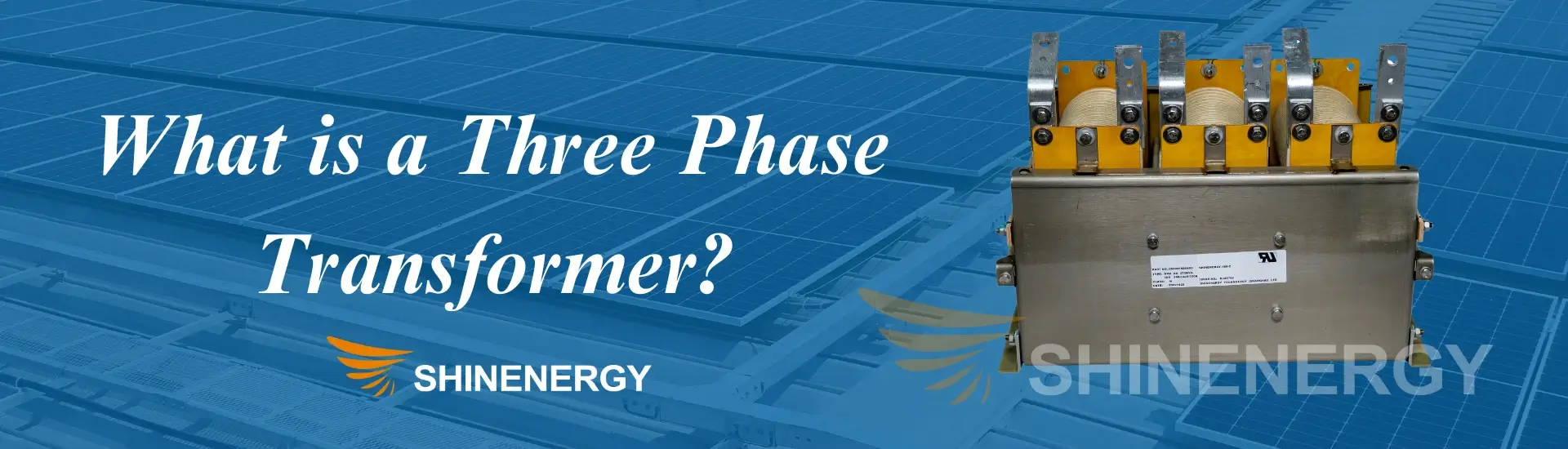
Figure 1-3 three phase transformer definition
A three-phase transformer is a device used in three-phase power systems. Three-phase transformers consist of three windings, each corresponding to one phase. It steps up or steps down voltage to meet different power requirements. It is widely used in power grids, factories, and commercial buildings to ensure stable electricity supply. Compared to single phase transformer to three phase, it offers higher efficiency and balanced power distribution.
Basic Working Principle of a Three-Phase Transformer
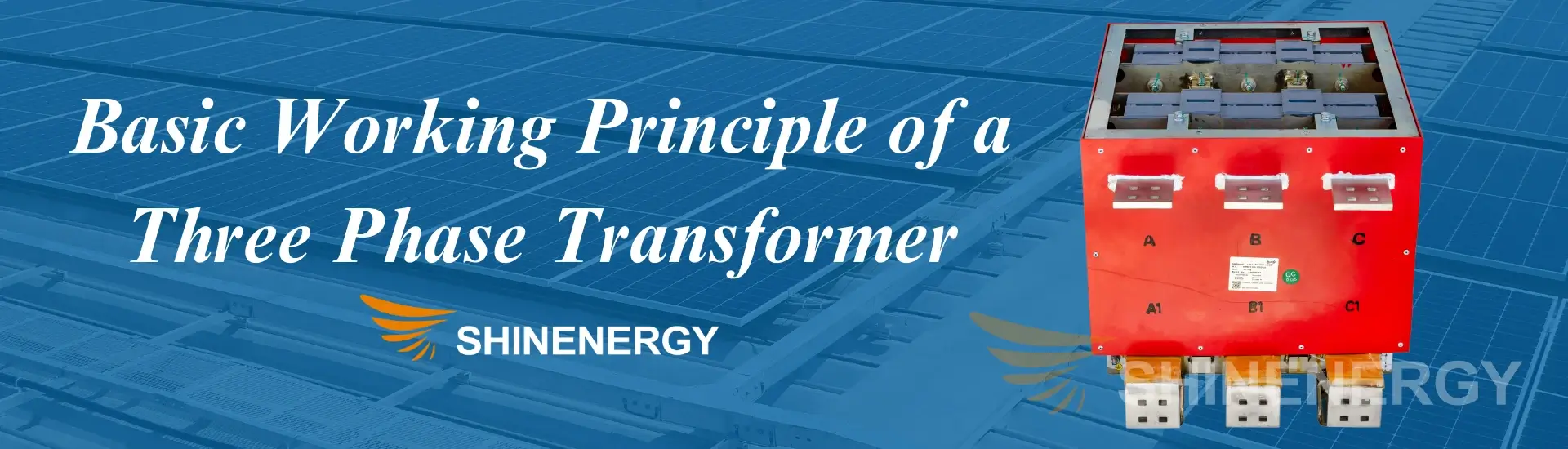
Figure 1-4 three phase transformer construction
A three-phase transformer operates based on electromagnetic induction. The primary winding receives AC power. The core transfers energy between windings. The secondary winding delivers the required voltage. The star (Y) or delta (Δ) connection determines how voltage and current are distributed. Different configurations suit different applications.
Difference Between Single Phase and Three Phase Transformer

Figure 2-1 single phase vs three phase transformer
Difference Between Three Phase and Single Phase Transformer: Characteristics and Applications of Single Phase Transformers
Single phase transformers handle lower power loads. They have one primary winding and one secondary winding. They step up or step down voltage for household and small commercial applications. Common uses include home appliances, lighting systems, and rural power distribution. They are simple, cost effective, and easy to maintain.
Difference Between Single Phase Transformer and Three Phase Transformer: Advantages and Disadvantages of Three Phase Transformers
Three phase transformers manage higher power loads. They distribute power evenly across three phases. This balance improves efficiency and reduces energy loss. They require less conductor material, lowering installation costs. However, they are more complex and expensive than single phase transformers. If one phase fails, the entire system may become unstable.
Which Transformer Suits Different Applications?

Figure 2-2 three phase transformer connection diagram
- Single phase transformers: Best for residential areas, small businesses, and low-power applications.
- Three phase transformers: Ideal for industrial plants, large commercial buildings, and power grids.
- If high efficiency and continuous power supply are priorities, three phase transformers are the better choice.
How Three Phase Transformers Work

Figure 3-1 three phase transformer bank
Basic Concept of Three Phase Power
Three phase power consists of three alternating currents. Each current is 120 degrees out of phase with the others. This setup ensures continuous power flow. It provides higher efficiency and smoother operation compared to single phase power. Most industrial and commercial systems rely on three phase power for heavy duty equipment.
Parts of a Three Phase Transformer
- Core: Made of laminated steel to reduce energy losses. It provides a path for magnetic flux.
- Primary Winding: Receives input AC power.
- Secondary Winding: Delivers the required output voltage.
- Insulation Material: Prevents short circuits between windings.
- Cooling System: Includes air, oil, or forced cooling to manage heat dissipation.
Energy Conversion Principle of a Three Phase Transformer
The transformer operates through electromagnetic induction. The primary winding receives an alternating voltage. This creates a magnetic field in the core. The field induces a voltage in the secondary winding. The turns ratio of the windings determines whether the transformer steps up or steps down the voltage. The star (Y) or delta (Δ) connection affects voltage and current distribution.
Types of Three Phase Transformers

Figure 4-1 three phase transformer sizes
Three Phase Transformer Chart
| three phase auto transformer | three phase isolation transformer | three phase buck boost transformer | three phase step down transformer |
| three phase pad mounted transformer | three phase distribution transformer | three phase current transformer | three phase power transformer |
| three phase pole mounted transformer | three phase dry type transformer | three phase pole mounted distribution transformer | three phase step up transformer |
| three phase pad mounted transformers | shell type three phase transformer | three phase control transformer | three phase delta transformer |
| three phase pad-mounted transformer | auto transformer three phase | core type three phase transformer | customized three phase current transformer |

Figure 4-2 three phase transformer chart
Three Phase to One Phase Transformer

Figure 4-3 three phase 480 to 120/240 transformer wiring
A three phase to single phase transformer converts three phase power into a single phase output. three phase single phase transformer is used when single phase loads need to operate within a three phase system. Various winding configurations, such as V-V connection, Scott-T connection, and open delta connection, facilitate this conversion. These single and three phase transformers help balance the electrical load while minimizing voltage fluctuations.
They are widely used in railway electrification, industrial machinery, and rural power distribution. In railway systems, they supply stable single phase power for trains running on AC networks. In industrial settings, they allow single phase equipment to function efficiently within a three phase infrastructure. In remote areas, single phasing a three phase transformer winding enable reliable power distribution where three phase supply is available but single phase demand exists.
These transformers improve energy efficiency, ensure stable voltage regulation, and reduce system imbalances. Their role is crucial in maintaining seamless power delivery for various applications.
Single Phase to Three Phase Transformer

Figure 4-4 single to three phase transformer
A one phase to three phase transformer rating converts single phase power into three phase output. single phase transformer to three phase allows three phase equipment to run in areas with only single phase supply. Common methods include phase converters, Scott T transformer single phase to three phase, and rotary phase converters. These single phase to three phase step up transformers power workshops, farms, and small factories. They improve motor efficiency, reduce power loss, and support higher loads. They provide a simple solution for industries needing three phase power.
What are The Various Types of Three Phase Transformer Connections
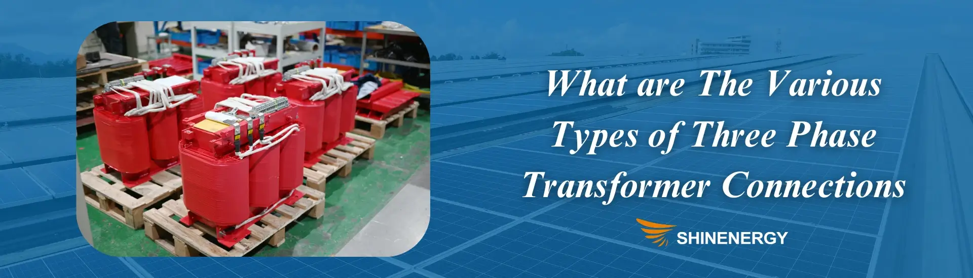
Figure 5-1 three phase transformer wiring
Star (Y) Connection vs. Delta (Δ) Connection
Figure 5-2 single phase to three phase transformer diagram
- Star (Y) Connection: Each phase winding connects to a common neutral point. This setup provides both line and phase voltage. It is ideal for longdistance power transmission because it reduces voltage stress on insulation.
- Delta (Δ) Connection: Windings form a closedloop triangle. No neutral point exists. This three phase transformer connections supports high current loads and reduces third harmonic currents. It is commonly used in industrial applications.
Characteristics and Applications of Y–Δ, Δ–Y, Y–Y, and Δ–Δ
Figure 5-3 three phase transformer delta-wye connection
- Y–Δ (Star–Delta): Steps down voltage. Common in power transmission and motor starting applications.a wye-to-delta connection may be made with three single-phase transformers
- Δ–Y (Delta–Star): Steps up voltage. Used in distribution transformer three phase to provide a neutral for residential loads.
- Y–Y (Star–Star): Balances voltage but requires load symmetry. It is less common due to voltage stability issues.
- Δ–Δ (Delta–Delta): delta delta connection of three phase transformerratings Provides high reliability. delta delta three phase transformer protection Continues operation even if one phase fails. Used in industrial and heavy machinery setups.
Choosing the Right Winding Configuration for Different Applications
- Power transmission: Y-Δ for stepping down voltage, Δ-Y for stepping up voltage.
- Industrial loads: Δ-Δ for high current applications, Y-Δ for efficient motor operation.
- Commercial and residential use: Δ-Y to provide a neutral connection for mixed loads.
- Unbalanced loads: Y-Y when load symmetry can be maintained.
Applications of Three Phase Transformer
Photovoltaic (PV) Solar Power
Figure 6-1 single phase transformer vs three phase transformer
Solar farms generate DC power, which must be converted to AC for grid integration. single phase and three phase transformer step up voltage to match transmission levels. They also stabilize voltage fluctuations caused by varying sunlight conditions. Grid tied solar inverters rely on these transformers for efficient energy distribution.
Energy Storage Systems (ESS)
Figure 6-2 120/208 three phase transformer bank
Battery storage systems store excess energy and release it when needed. Three phase transformer protection regulate voltage between batteries and the grid. They enable smooth power transfer between charging and discharging cycles. Their role is crucial in stabilizing power grids with intermittent renewable energy sources.
Wind Energy

Figure 6-3 120/208 three phase transformer wiring diagram
Wind turbines generate electricity at varying voltages. Three phase transformers step up voltage for long distance transmission. They also balance power fluctuations caused by wind speed variations. Offshore and onshore wind farms depend on these transformers for reliable grid integration.
Data Centers

Figure 6-4 20kva three phase transformer
Data centers require stable and uninterrupted power. Three phase transformers distribute power efficiently across servers and cooling systems. They regulate voltage fluctuations and prevent power surges. Their high efficiency reduces energy losses, improving overall power system reliability.
New Energy Vehicles (NEV) and Charging Stations

Figure 6-5 230 volt single phase to three phase transformer
Electric vehicle (EV) charging stations demand high power capacity. Three phase transformers step down grid voltage for fast charging infrastructure. They ensure safe and efficient power delivery to multiple charging units. Their integration optimizes energy use in smart charging networks.
Medical Industry

Figure 6-6 480 to 208 three phase transformer
Hospitals and medical equipment require clean and stable power. three phase transformer core supply voltage to MRI machines, CT scanners, and operating rooms. They eliminate electrical noise and ensure reliable performance of sensitive medical devices. Uninterrupted power supply is critical for emergency and intensive care units.
Three phase core type transformer support various industries by ensuring efficient power distribution, voltage regulation, and energy stability. Their applications continue to expand with advancements in renewable energy and smart grid technology.
Parallel Operation of Three Phase Transformers
Figure 7-1 single phase three phase transformer
Conditions for Parallel Operation
Figure 7-2 parallel operation of three phase transformer pdf
For three phase transformer delta wye connection to operate in parallel, they must meet specific conditions to ensure stable and efficient power distribution. The voltage ratio must be the same to prevent circulating currents and allow balanced load sharing. The phase sequence must match to avoid short circuits, and the phase angle should align to prevent out of phase operation, which can cause system instability. Similar impedance values are also necessary to ensure proportional load distribution between transformers and avoid overload on a single unit.
Advantages and Disadvantages of Parallel Operation
Figure 7-3 50 kva three phase transformer
Parallel operation offers several benefits, including improved reliability, as one transformer can continue functioning if another fails. It also provides scalability, allowing additional transformers to be added when power demand increases. Better load management ensures even power distribution across multiple units, while optimized transformer loading enhances overall efficiency and reduces energy losses. However, there are also disadvantages, such as unequal load sharing when impedance values differ, which can lead to unbalanced operation. Mismatched voltage ratios can cause circulating currents, reducing efficiency. Additionally, synchronization and monitoring systems add complexity to the overall setup.
Applicable Scenarios and Industry Cases
Figure 7-4 three phase transformer nameplate
Parallel operation of transformers is widely used in various industries to enhance power reliability and flexibility. Power grids utilize parallel transformers to handle fluctuating energy demands efficiently. Industrial plants with variable loads benefit from load sharing capabilities, ensuring stable power distribution. Renewable energy systems, including wind and solar farms, integrate multiplethree phase transformer design to maintain grid stability. Data centers rely on parallel transformers for redundancy, preventing power disruptions during maintenance. EV charging stations require parallel transformers to support high power fast charging networks, ensuring efficient energy delivery for electric vehicles.
Efficiency and Losses in Three Phase Transformers
Figure 8-1 480 to 240 three phase transformer
Copper Loss vs. Core Loss
Copper loss occurs due to the resistance in transformer windings, parts of three phase transformer increasing with higher load currents and dissipating energy as heat. Core loss includes hysteresis loss, caused by repeated magnetization and demagnetization, and eddy current loss, which results from circulating currents in the core material. Both losses impact transformer efficiency and energy consumption.
Factors Affecting Efficiency
Three-phase transformers efficiency depends on multiple factors, including load conditions, core material, winding resistance, cooling systems, and winding configurations. High loads increase copper loss, while light loads can lead to poor efficiency. High quality core materials reduce hysteresis and eddy current losses. Lower resistance windings improve efficiency by minimizing copper loss. Proper cooling systems prevent overheating, and optimized winding designs reduce unnecessary energy waste.
How to Improve the Efficiency of Three Phase Transformers
Efficiency improvements include using low resistance windings to minimize copper loss and selecting high quality core materials such as amorphous metal or silicon steel to reduce core loss. Optimized cooling systems, including air, oil, or forced cooling, help maintain performance. Managing transformer loads effectively ensures they operate near optimal capacity, minimizing energy waste. Regular maintenance prevents insulation degradation, overheating, and efficiency loss, ensuring long term reliability and energy savings.
Future Trends in Three Phase Transformers

Figure 9-1 transformer diagrams three phase
Development of Green and Energy Efficient Transformers
With increasing emphasis on energy conservation and carbon reduction, green and energy efficient transformers are becoming a key trend. These transformers use advanced design techniques to minimize losses and improve overall efficiency. Regulatory policies worldwide are pushing for eco-friendly transformer technologies that reduce environmental impact while maintaining high performance. Energy-efficient transformers not only lower operational costs but also enhance grid stability and sustainability.
Application of New Materials such as Amorphous Alloy Cores
Innovations in transformer materials are significantly improving efficiency and performance. Amorphous alloy cores, known for their lower hysteresis and eddy current losses, are gaining popularity in transformer manufacturing. These materials reduce core losses by up to 70% compared to traditional silicon steel cores, making them ideal for high efficiency applications. And The adoption of advanced insulation and cooling technologies further enhances transformer lifespan and reliability, ensuring stable operation in modern power systems.
Development of Digital and Smart Transformers
Digital and smart transformers are revolutionizing power distribution and management. Equipped with sensors, IoT connectivity, and real time monitoring systems, these transformers provide predictive maintenance, fault detection, and remote control capabilities. Smart transformers enhance grid automation, enabling dynamic voltage regulation and load balancing. With the integration of AI and big data analytics, future transformers will optimize power flow, reduce downtime, and improve energy efficiency across various applications, including renewable energy integration and smart grid systems.
FAQs About Three Phase Transformers
How do you perform three phase transformer calculations using the three phase transformer calculation formula, and is there a three phase transformer calculator or three phase transformer sizing chart available?
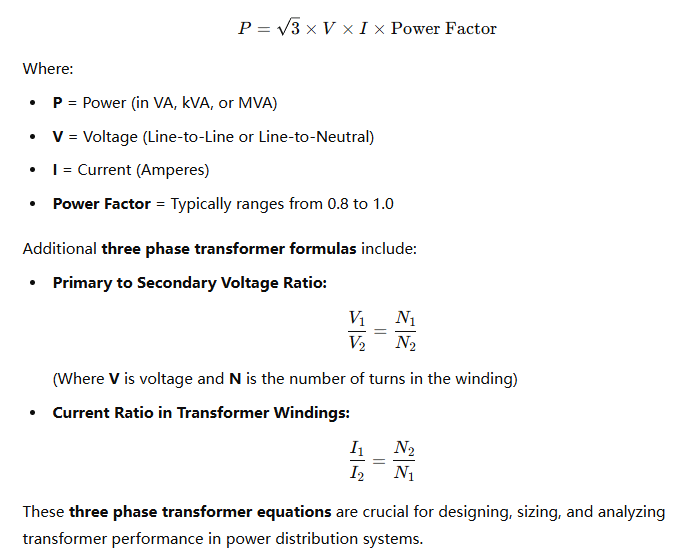
Performing three phase transformer calculations requires using the three phase transformer calculation formula to determine power ratings, current, and voltage relationships. The fundamental formula for three-phase power is:
Where:
P = Power (VA, kVA, or MVA)
V = Voltage (Line-to-Line or Line-to-Neutral)
I = Current (Amperes)
Power Factor = Typically ranges from 0.8 to 1.0
For precise calculations, you can use three phase transformers calculator, which simplifies the process by automatically computing values based on input voltage, power rating, and power factor. Additionally, a three phase transformer sizing chart provides standard transformer ratings. And helps to select the appropriate transformer size based on load requirements.
Using a three phase transformer sizing chart, engineers can quickly match their system’s power demands with the correct transformer size, ensuring efficiency and reliability in power distribution.
What are the three phase transformer equations, and how do the three phase transformer formula and three phase transformer formulas apply to transformer calculations?
The three phase transformer equations are essential for calculating power, voltage, and current in a three-phase electrical system. The key three phase transformer formula used in power calculations is:
Pingback: เว็บตรงฝากถอนง่าย
Pingback: HILO789
Pingback: โปรเน็ตบ้าน true
Pingback: โคมไฟ
Pingback: Western Love-Making and Sex