When we energize the transformer, we often encounter a phenomenon called “inrush current”. This current is several times larger than the transformer’s normal operating current, like a momentary “current shock”, the power system and equipment will bring a lot of pressure. Surge current may not only make the equipment overloaded but, in severe cases will also make the circuit breaker tripped, and even affect the stability of the entire system.
So, how do we deal with this problem? Don’t worry, this article will help you gain an in-depth understanding of the causes of inrush surge current, the various problems it can cause, and the simple and effective control methods we can take to ensure a more stable and secure power system.

Figure 1 What is inrush current
What is transformer inrush current?

Figure 1-1 define inrush
Transformer inrush current is simply when we connect the transformer to the power, the instantaneous generation of a very large current, motor start-up current, many times larger than the transformer’s normal operation current. This phenomenon usually occurs in the transformer just starting the moment, because the transformer’s internal core will be for a short period of time “magnetized” to the limit, also known as the core saturation, resulting in a surge of current.
To make an analogy, in a transformer starting current, the current inrush is like you turn off the faucet after a long time suddenly opening, the water pressure is particularly large, and the water gushes out. Transformer inrush current is the same reason: at first the current will surge, but after a period of time, the current will gradually return to normal. Although the inrush current lasts only a few seconds, if it is not controlled, it may affect the stability of the power system or even damage the equipment.
Why do transformer surges occur?
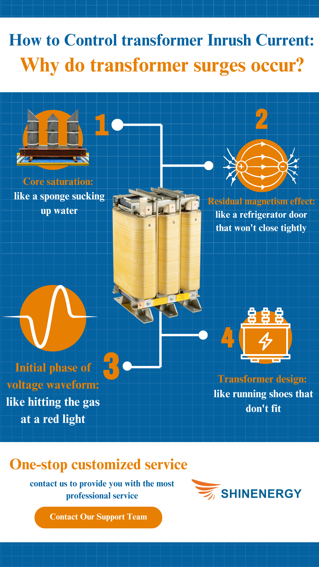

Figure 2-1 inrush meaning
Core saturation: like a sponge sucking up water

Figure 2-2 current transformer project
Imagine you take a dry sponge and absorb water, at first the water will be absorbed quickly, and the sponge’s ability to absorb water is particularly strong. But when the sponge is almost full of water, the water will start to overflow and can no longer be absorbed. The transformer core in the first start-up is similar, the current like water in the core, but when the core “saturation”, the magnetic flux can no longer flow as normal, and the current growth will suddenly become very large, this instantaneous increase in current will be higher than the normal operation of the current by several times, or even dozens of times. It is like a sponge that can no longer absorb water.
Residual magnetism effect: like a refrigerator door that won’t close tightly

Figure 2-3 current transformer orientation
You’ve probably had the experience of not closing the refrigerator door tightly and leaving cold air inside. The next time you open the refrigerator, the refrigeration system will work harder and the temperature will adjust more slowly. This is what is meant by the “remanent magnetization effect” of a transformer. After the transformer is powered off, there is still some “magnetism” left inside, and when you start it up again, this residual magnetism and the new magnetism are superimposed together, resulting in an instantaneous surge of current, which further exacerbates the degree of saturation of the magnetic core, thus generating a larger inrush of current. Especially when the transformer does not undergo sufficient demagnetization process, the residual magnetism effect will be particularly obvious, as if the transformer is “overloaded” for a period of time.
The initial phase of voltage waveform: like hitting the gas at a red light

Figure 2-4 inrush current calculator
Imagine again that you’re waiting at a stoplight, and if you step on the gas too hard, the car will lurch out. The same thing happens with voltage waveforms. If you start the transformer at the peak or trough of the voltage, just like starting it when the gas pedal is pressed to the floor, the current will rush to its maximum value at once, resulting in a particularly high inrush current. If you start it in a smooth state, the inrush current is not as strong.
Transformer design: like running shoes that don’t fit

Figure 2-5 Transformer curve
Suppose you buy a pair of ill-fitting running shoes, which are uncomfortable to run in and prone to injury. The same is true for transformer design. If the core material, size, or winding design of the transformer is not reasonable, the inrush current will be like running in ill-fitting shoes, and the problem will be even more serious, and the inrush current when the transformer starts up will be particularly high. Therefore it is especially important to have a professional team to protect you.
Effects of Transformer Inrush Currents
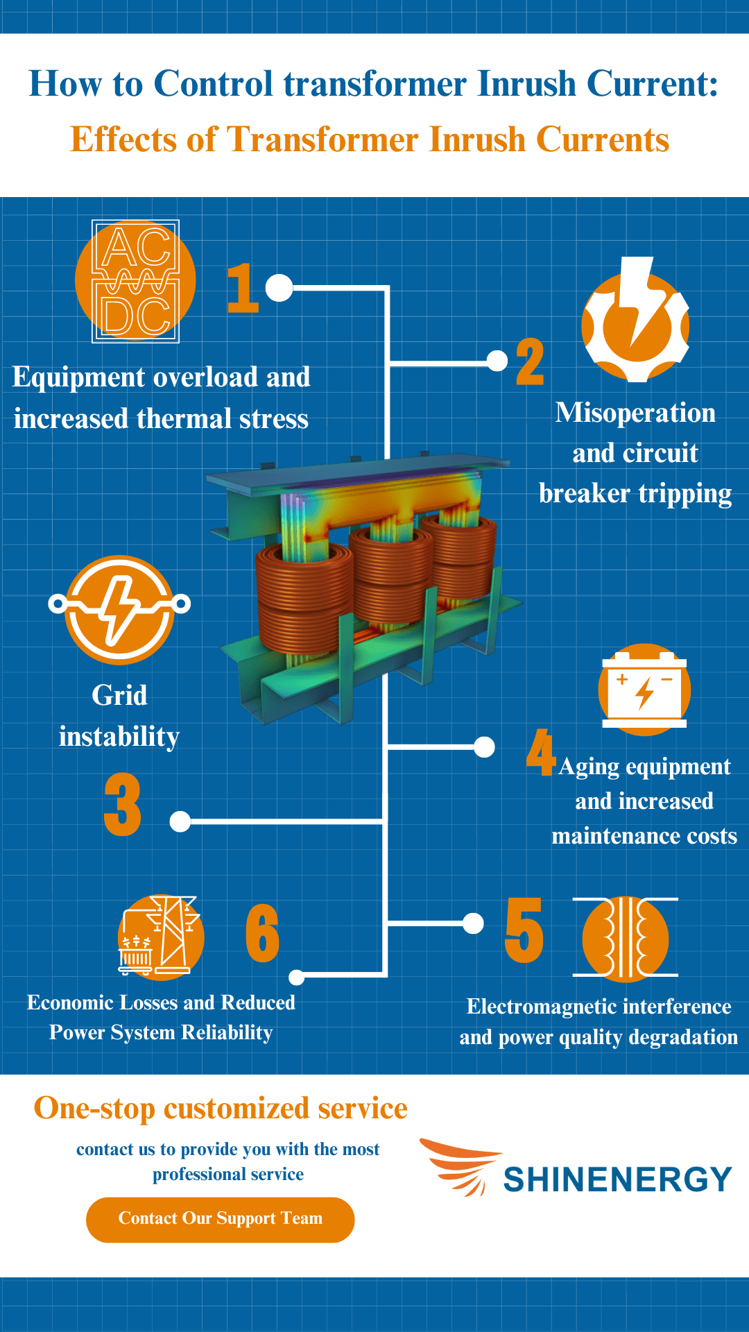
Figure 3-1 inrush current of transformer
Equipment overload and increased thermal stress

Figure 3-2 All values of a transformer are proportional to its
The magnitude of the rush current is usually several times the rated current of the transformer, which can cause the equipment to be subjected to tremendous overload pressure for a short period of time. Excessive current generates excessive heat, causing the temperature of the transformer’s windings and core to rise dramatically, which in turn increases the deterioration of the transformer’s internal insulation. The transformer and the equipment in the power system are burdened with a much larger than usual current. As if your home appliances suddenly power surge, long-term in this state will shorten the service life of the equipment, and may even directly damage the equipment. In particular, protective devices such as circuit breakers will be forced to trip frequently due to overloading.
Misoperation and circuit breaker tripping

Figure 3-3 Transformer breaker sizing chart
A sudden increase in inrush current can easily be misjudged as fault current by the protective equipment in the power system, especially if no protection mechanism is in place for the inrush current. Circuit breakers may trip unnecessarily, leading to unwanted power interruptions and affecting the reliability of system operation. This type of misoperation can lead to frequent power outages and equipment restarts, which not only affects system efficiency but also increases wear and tear on the equipment.
Grid instability

Figure 3-4 inrush current protection circuit
Inrush currents can trigger transient voltage dips and harmonic distortions in the power system. Particularly when large transformers are connected to the grid, inrush currents can cause significant voltage fluctuations that adversely affect other sensitive loads in the power network. Just like when you suddenly apply the brakes while driving and the car becomes unstable or even out of control, voltage instability can lead to system frequency fluctuations and affect the normal operation of other loads in the distribution system, increasing the risk of system imbalance.
Aging equipment and increased maintenance costs

Figure 3-5 Transformer damage curve
Due to the large mechanical and electromagnetic stresses generated by the inrush current, the transformer core and windings are subjected to additional mechanical impacts, and the internal mechanical structure and insulation system of the equipment will gradually deteriorate under repeated action over a long period of time. Insulation materials will deteriorate under repeated thermal shock and electromagnetic stress, thus increasing the equipment failure rate and maintenance costs. In addition, the frequency of regular overhauls and replacement of equipment will be increased as a result, increasing the operating costs of the entire power system.
Economic Losses and Reduced Power System Reliability

Figure 3-6 Transformer AC current
Frequent power outages and unstable grid operations can have a direct economic impact on businesses and industrial users. Unscheduled outages caused by inrush currents can disrupt production processes and cause productivity losses, especially for industrial sectors that rely on a continuous supply of electricity. In addition, frequent equipment failures and maintenance can increase operating costs, further impacting the overall economics and reliability of the power system.
Electromagnetic interference and power quality degradation

Figure 3-7 Generator vs transformer
The Inrush current of a transformer can trigger short periods of electromagnetic interference, especially in the high-frequency section. This EMI not only affects other electrical equipment in the vicinity of the transformer but may also affect the power quality of the entire grid through conduction or radiation paths. The degradation of power quality can lead to a reduction in the effective utilization of electrical energy, affecting the stability of the system and the normal operation of electrical equipment.
How to calculate the inrush current of a transformer?
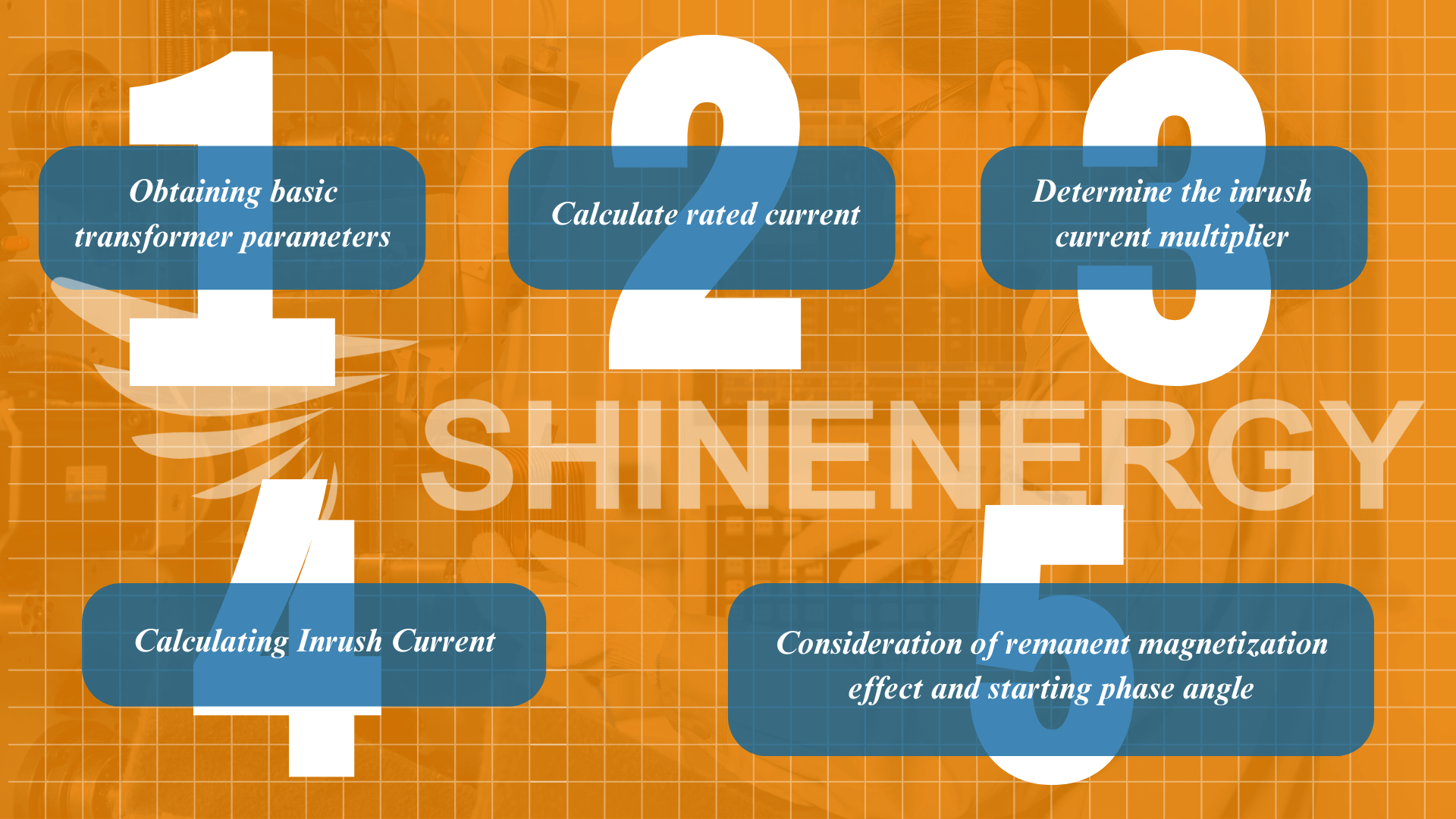
Figure 4-1 inrush current calculation
Getting the necessary parameters
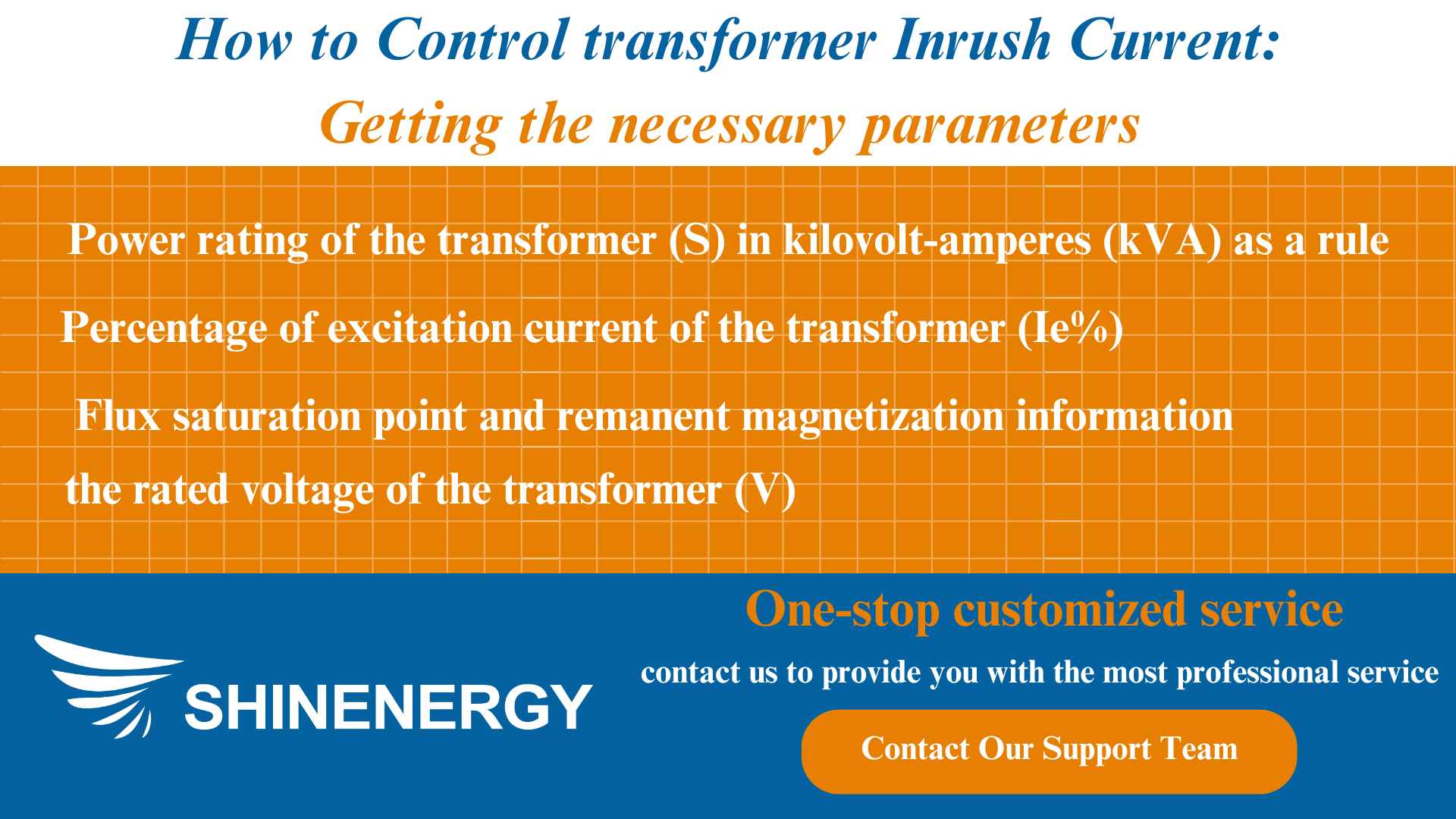
Figure 4-2 inrush calculator
Before calculating the inrush current, it is first necessary to obtain the basic parameters of the transformer:
- the rated voltage of the transformer (V)
- Power rating of the transformer (S) in kilovolt-amperes (kVA) as a rule
- Percentage of excitation current of the transformer (Ie%)
- Flux saturation point and remanent magnetization information
Estimation formula for inrush current
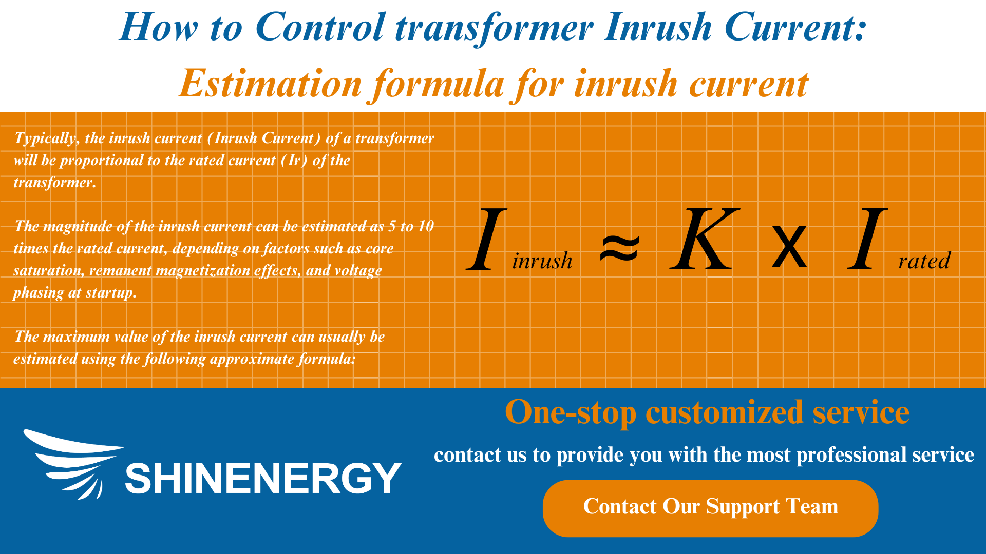
Figure 4-3 Transformer primary fuse size calculator
Typically, the in-rush current (Inrush Current for transformer) of a transformer will be proportional to the rated current (Ir) of the transformer. The magnitude of the inrush current can be estimated to be 5 to 10 times the rated current, depending on factors such as core saturation, remanent magnetization effects, and voltage phase at startup.
The maximum value of the high tide current can usually be estimated using the following approximate formula:
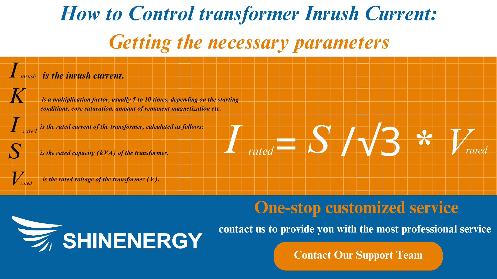
Figure 4-4 Transformer inrush current calculation
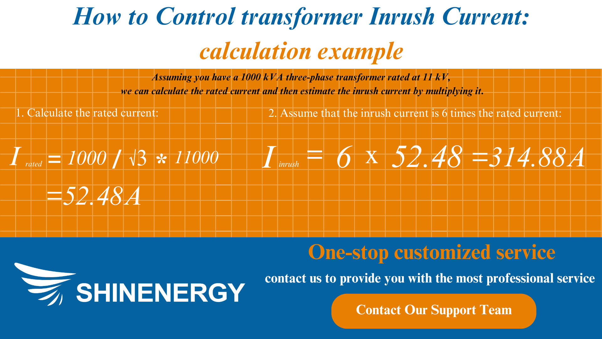
Figure 4-5 Transformer inrush calculation
How to Measure Inrush Current?
Use of oscilloscopes
An oscilloscope can monitor the current waveform in real-time. During transformer startup, connect a current probe to the transformer input and record the current waveform at the moment of startup. With an oscilloscope, you can see the magnitude and duration of the inrush current as well as its waveform characteristics calculating the transformer inrush current.
Using a digital ammeter
Many digital ammeters have a peak hold function that can be used to capture the maximum current at startup. Connect the ammeter to the input circuit of the transformer, and when the transformer is started, the ammeter will display the maximum instantaneous current at startup.
Use a specialized inrush current tester
Specialized inrush current testers can specifically measure the inrush current in a circuit during startup. These devices can automatically record the peak value and waveform of the inrush current, which is easy to operate and provides accurate results.
Measurement of voltage waveform and phase
Combine voltage waveform measurement tools to determine the voltage phase at startup, as the startup phase angle can have a large impact on the inrush current calculated transformer inrush current.
How to Reduce Transformer Inrush Current
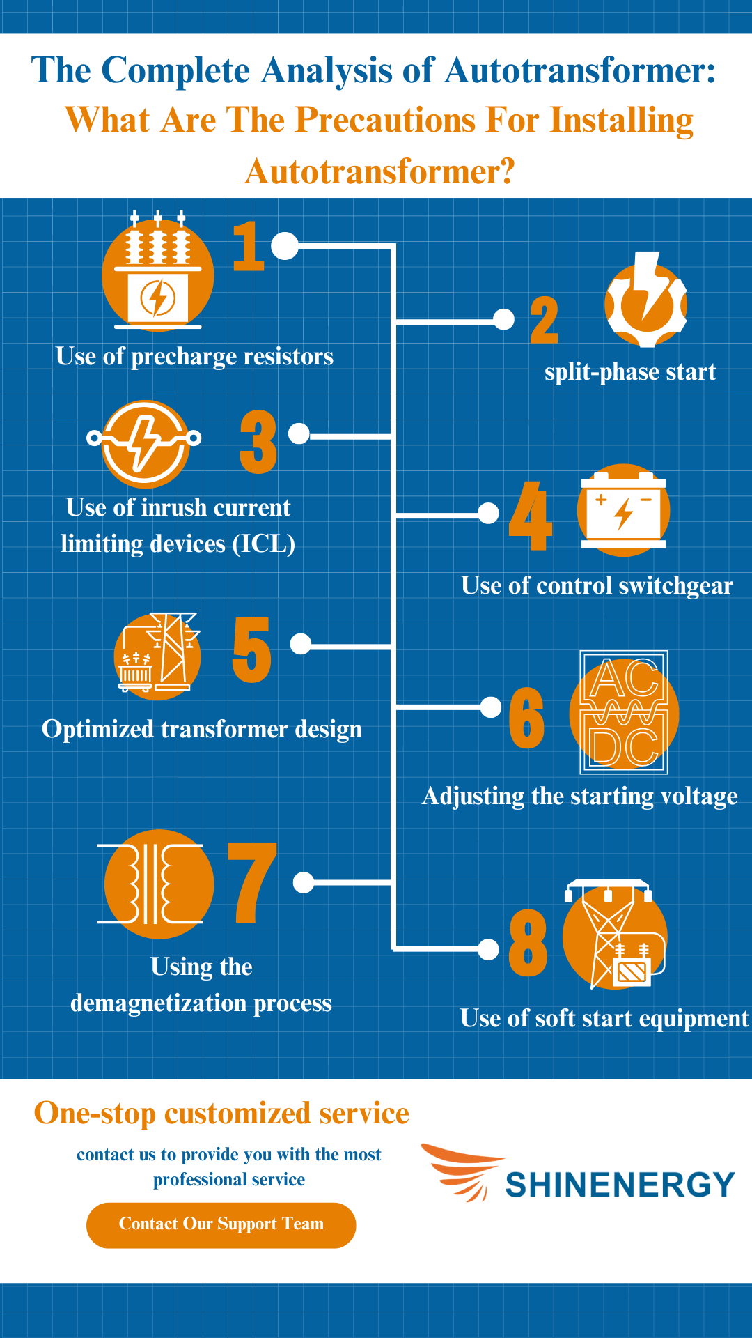
Figure 5-1 Transformer inrush currents
Use of precharge resistors

Figure 5-2 Transformer drawing
Adding a pre-charging resistor before transformer overcurrent protection is energized can effectively reduce the inrush current during startup. Pre-charging resistor gradually increases the current, so that the transformer will not be damaged by the sudden high current impact, especially suitable for high-voltage and large-capacity transformer startup. This not only protects the equipment but also makes the whole starting process smoother and avoids excessive burden on the power system.
split-phase start

Figure 5-3 transformer current
Split-phase startup reduces the current shock during startup by allowing different phases of the transformer to be gradually connected to the grid, avoiding all phases being energized at the same time. The current superimposed on each phase is more uniform, effectively reducing the peak value of the inrush current. This method is particularly suitable for three-phase transformer startup, which can reduce the impact of inrush current on the system and ensure the safe operation of the transformer and power system.
Use of inrush current limiting devices (ICL)

Figure 5-4 draw transformers
Inrush current limiting devices/ inrush current limiter (ICLs) control the rate of current inflow during transformer startup to avoid sudden current surges. These devices exit the circuit after the current has stabilized, ensuring that the transformer and system are not subjected to excessive transients.ICLs are suitable for applications where tight control of the inrush current is required, and are particularly suited to the protection of sensitive power equipment.
Use of control switchgear

Figure 5-5 Transformer magnetism
By controlling switching equipment such as intelligent circuit breakers, transformer breakers, and thyristor switches, the starting moment of the transformer can be optimized according to the phase of the voltage waveform, avoiding starting at the peak of the voltage wave. This technique effectively reduces the current impact during start-up and improves the stability of the system, which is particularly suitable for the start-up process of large transformers, thus reducing the impact on the power network.
Optimized transformer design

Figure 5-6 how to draw transformers step by step
By optimizing the design of the transformer and using low-loss core materials, the saturation degree of the transformer core can be reduced, thus reducing the inrush current. In addition, the rational design of the winding structure and magnetic circuit layout can also effectively reduce the inrush current at startup. This method is applicable to transformers for new or renewed equipment and can prolong the service life of the equipment and improve operational stability.
Adjusting the starting voltage

Figure 5-7 in rush current
Gradually increasing the voltage at transformer startup, rather than applying the full voltage at once, can effectively reduce the inrush current. By reducing the initial starting voltage, the transformer is able to transition smoothly to the normal operating state, thus reducing the current impact. This method is similar to soft-start equipment, especially widely used in power systems with voltage regulation, and can protect the transformer well.
Using the demagnetization process

Figure 5-8 What is inrush
When a transformer is de-magnetized, it may leave residual magnetic fields, resulting in a higher inrush current at the next startup. By performing a demagnetization operation at power failure, this residual magnetism can be eliminated, reducing the inrush current at the next start-up. Especially in large-capacity transformers, the demagnetization process can significantly improve the current waveform at startup and reduce system inrush.
Use of soft start equipment

Figure 5-9 What is the inrush current
Soft start equipment can control the starting process of the transformer by gradually increasing the current to avoid transient high current impact. Soft start can make the starting process smoother, reduce the impact of inrush current on equipment and protect other equipment in the power system. It is very suitable for the starting of high-power and heavy-load transformers, which can ensure the stability and safety of the power system.
Use of step-up transformers

Figure 5-10 Does a step up transformer increase current
The step-up transformer can reduce the inrush current impact during direct start-up by first gradually increasing the voltage and then steadily outputting it to the target transformer. This approach not only improves the efficiency of system operation but also ensures a steady increase in current, so that the transformer gradually enters the working state in a smooth voltage boosting process, avoiding instantaneous excessive current during start-up. Step-up transformers are suitable for applications with high requirements on power quality, such as the power supply of large-scale industrial equipment or sensitive electronic equipment.
Conclusion

Figure 6 What is an inrush current
In order to effectively control and reduce the inrush current of the transformer and ensure the safety and stability of the power system, it is crucial to choose the appropriate methods and equipment. Whether it is the use of pre-charge resistors, split-phase starting, inrush current limiting devices, or optimized transformer design, each method needs to be selected and configured appropriately based on actual equipment requirements and application scenarios. For this reason, it’s important to consult with a team of power technology professionals who can provide customized solutions for specific power systems.
If you are looking for a reliable power solution provider, Shinenergy is a recommended choice. As a leading company in the industry, Shinenergy specializes in the design and manufacture of custom transformers and related power equipment, offering a variety of services including step-up transformers, inrush current management solutions, and more. With their extensive experience and professional team, they are able to help customers develop efficient and stable power system solutions to ensure the safety and reliability of their equipment for long-term operation.
FAQ
What is NTC for inrush current protection?
NTC thermistors are used for inrush current protection, limiting the current at startup by their initial high resistance. As the circuit operates, the resistance decreases as the temperature rises, allowing the current to gradually return to normal, protecting the equipment from ntc inrush current limiter.
How do you limit inrush current?
- NTC Thermistors: Initially provide high resistance to limit the inrush current, which decreases as the thermistor heats up.
- Pre-charge Resistors: Gradually charge capacitors by adding resistance in the circuit during power-up.
- Soft Starters: Gradually increase the voltage to motors or transformers, avoiding a sudden surge in current.
- Inrush Current Limiters (ICL): Specialized devices that control the initial current surge.
- Controlled Switching: Use switches to control when power is applied, avoiding switching at high points in the voltage waveform.
- Sequential Phase Energization: In three-phase systems, energize phases one by one to spread out the current demand.
What is the difference between NTC and PTC for inrush current?
NTC thermistors start with high resistance to limit inrush current, and their resistance decreases as they heat up.
PTC thermistors start with low resistance and increase resistance as they heat up, mainly for overcurrent protection rather than inrush current control.

